Scratchbuilders!
Built a model or part from your own materials lately?
Hosted by Mike Kirchoff
1/24 Leyland DAF DROPS Update
okdoky
Visit this Community
Scotland, United Kingdom
Member Since: April 30, 2007
entire network: 1,597 Posts
KitMaker Network: 673 Posts
Posted: Wednesday, August 11, 2010 - 03:02 PM UTC
Apart from pivot brackets still trying to pop off again I am really chuffed with my latest bit of work as I have turned my hand to a little bit of simple soldering. I say simple now because before today, I had not ever tried it even though I have had my dads old soldering irons in my shed for years. I bought myself a new set from Lidls and took it upt on holiday with me.

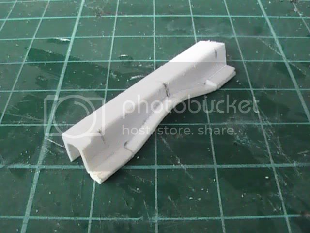
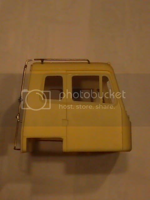
Kaz and the girls tucked up in bed so I have had no distractions whilst setting about the cab ladder and grab rails. I am pleased to admit that it is far easier than I had anticipated and now I will be able to add this to my list of techniques still to use to its fullest.

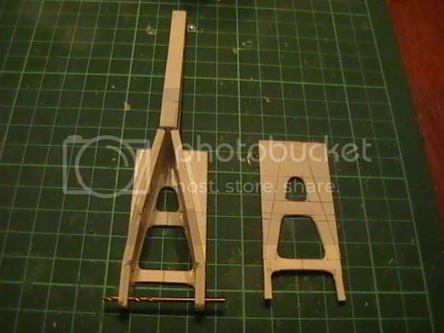
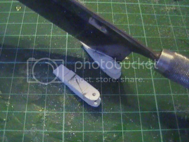
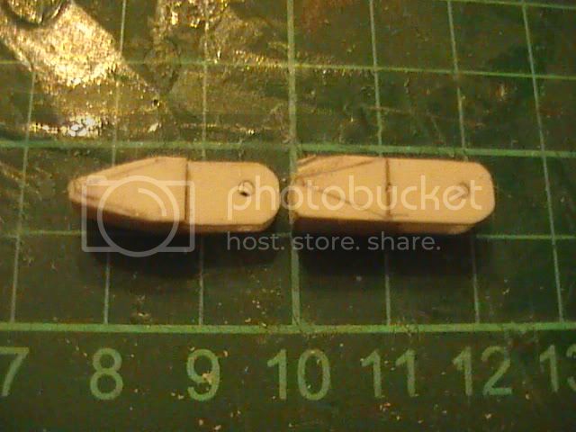
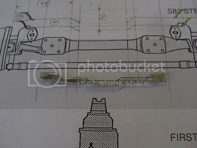
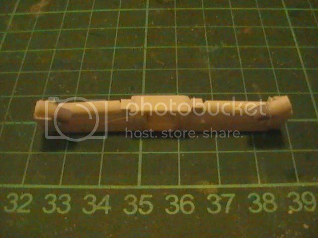
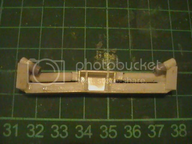
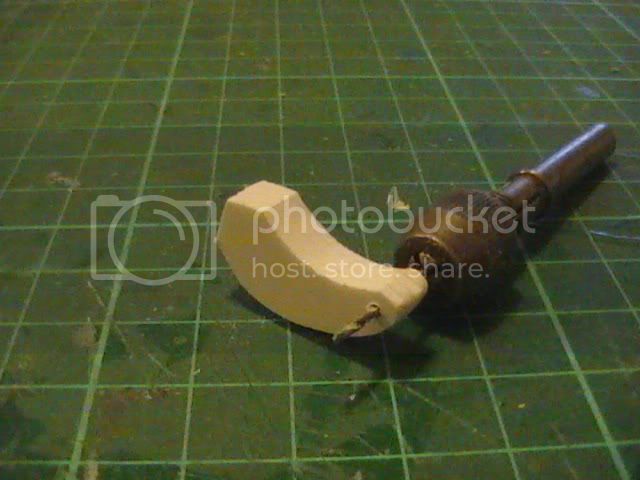
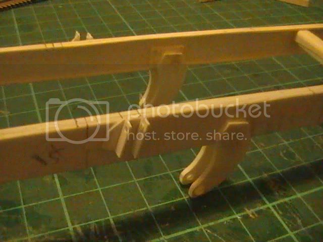
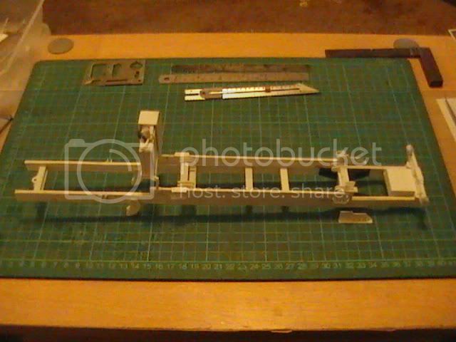
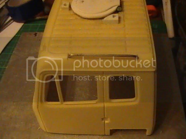
First a bit of simple bar bending


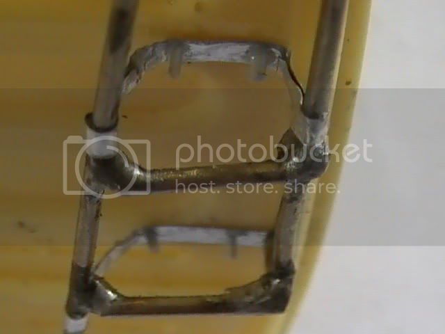
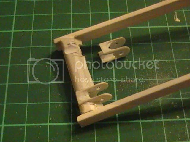
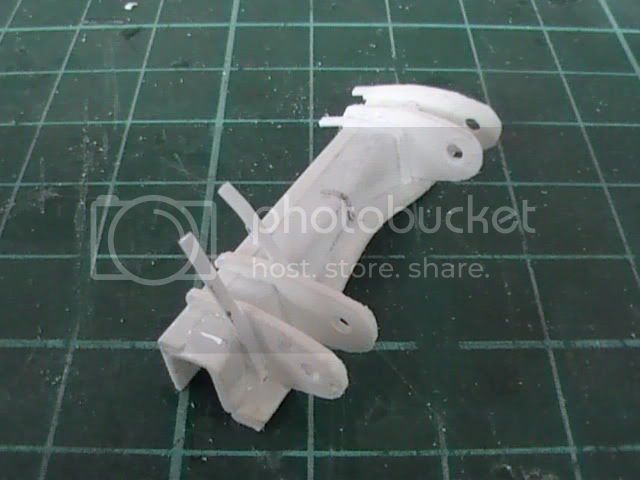
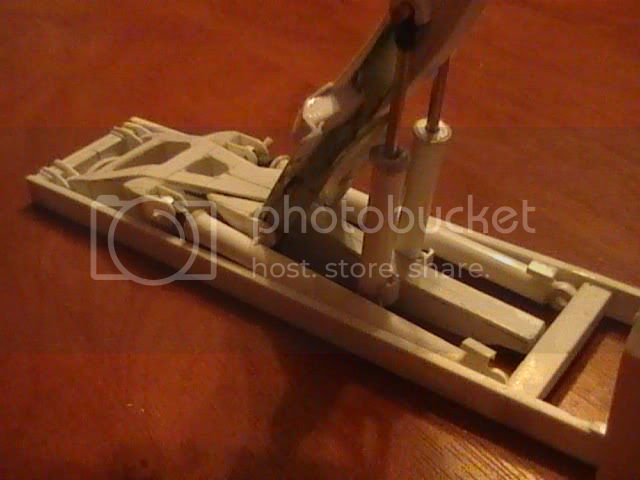
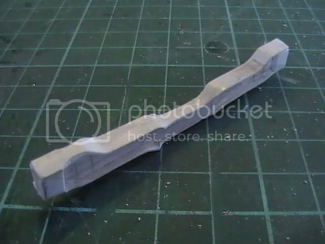
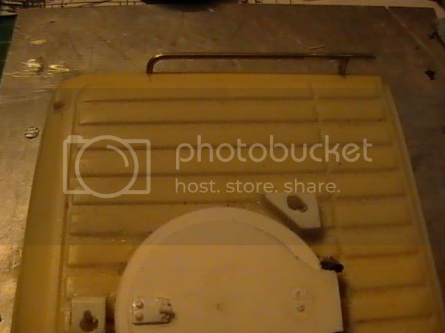
Then my first ever solder


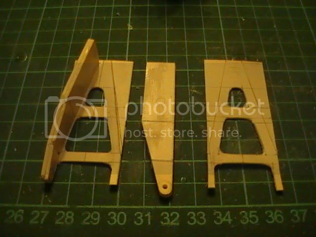
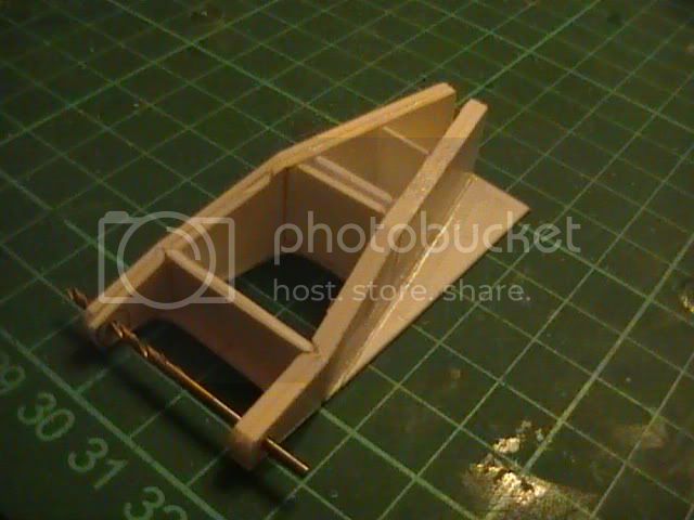
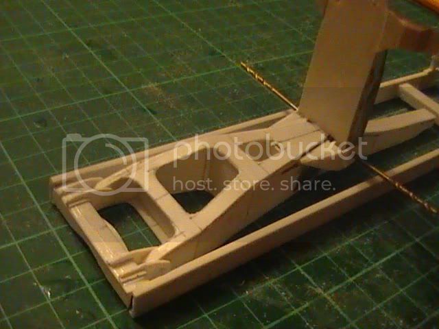
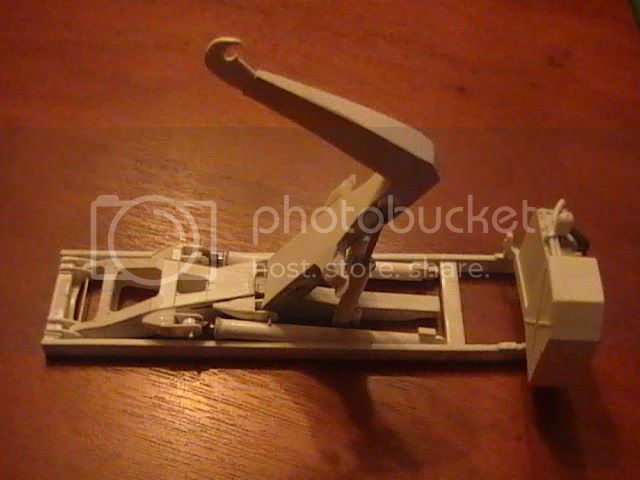
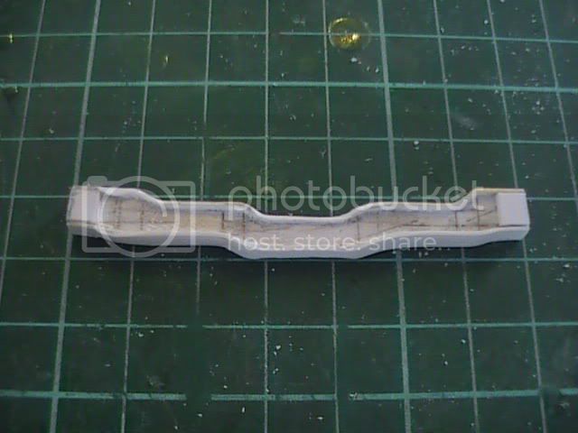
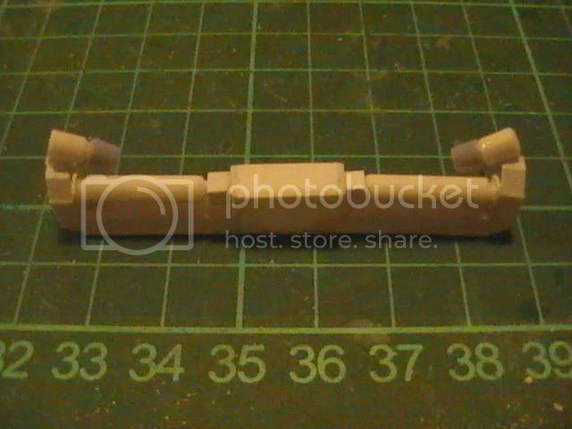
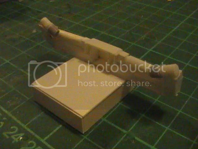
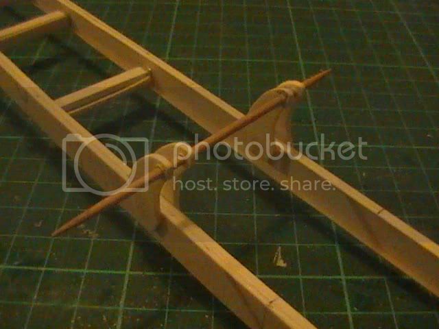
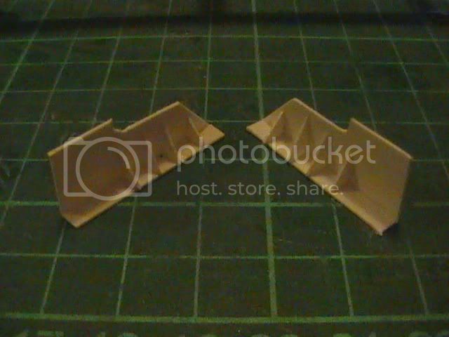
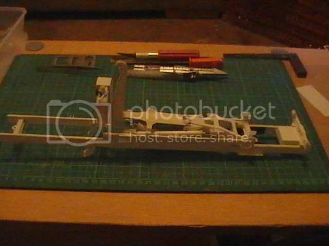
Then the bit more complicated (for me anyway) ladder with its bends and dimensions judged from various photos


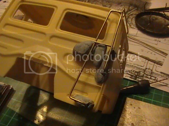
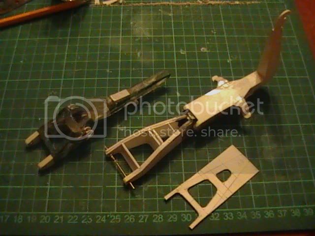
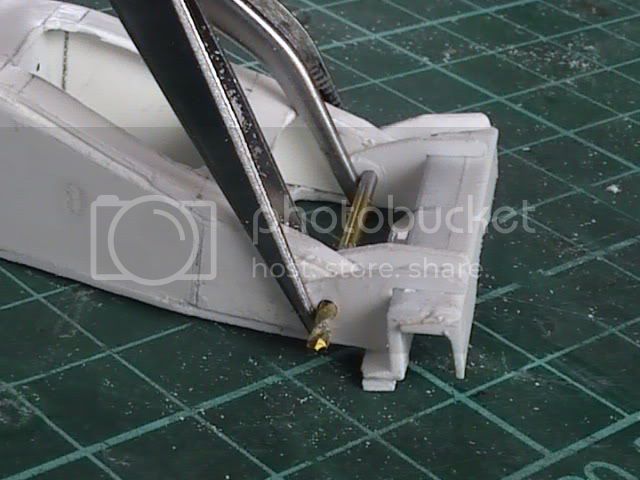
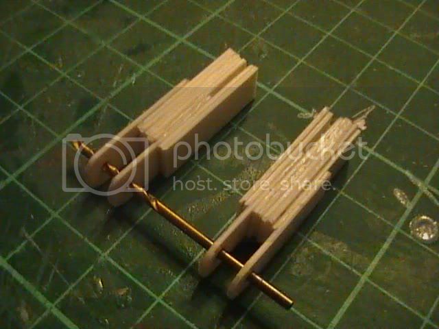
I found that blue-tac and crocodile clips are great tools for holding parts in place for soldering


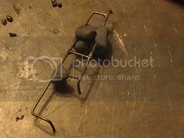
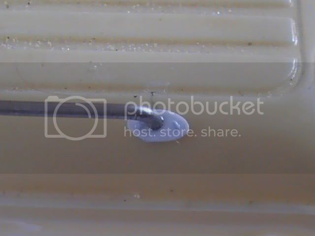
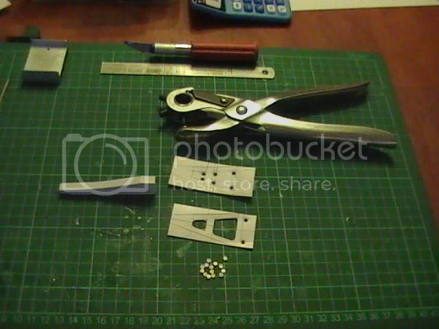
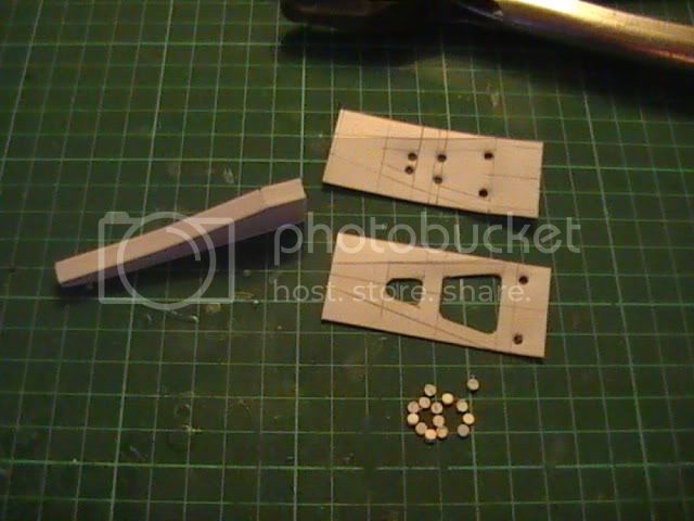
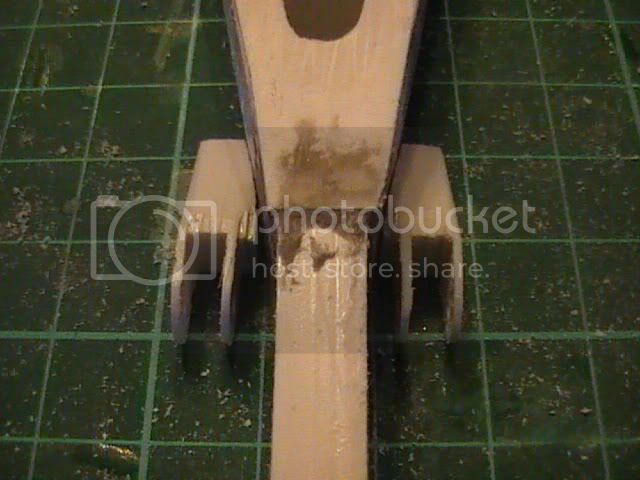
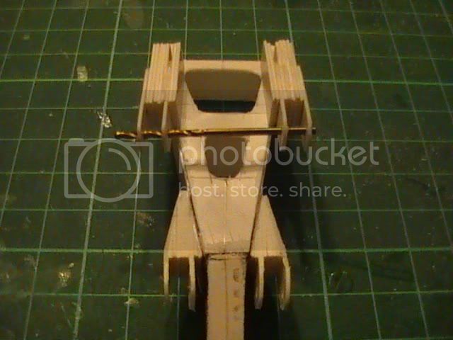
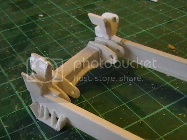
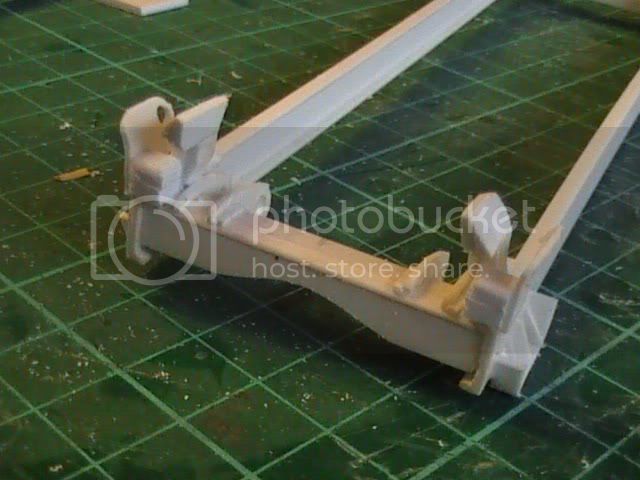
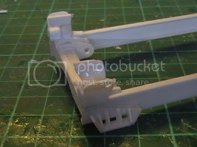
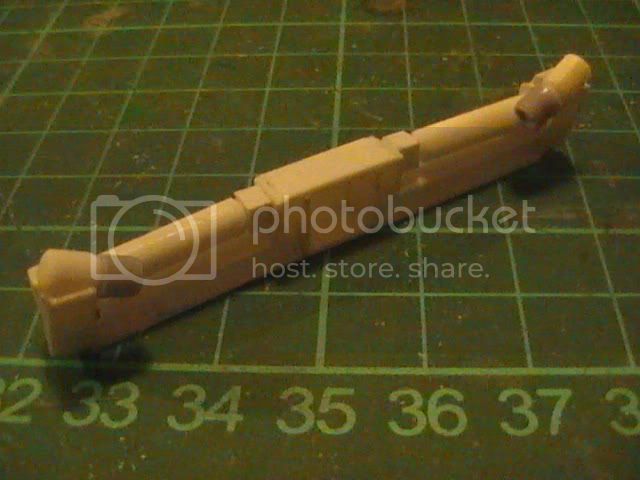
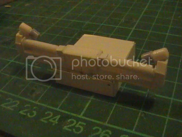
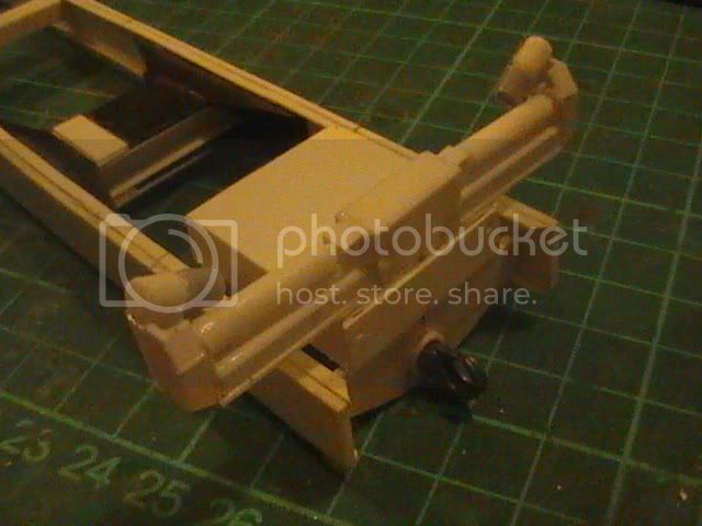
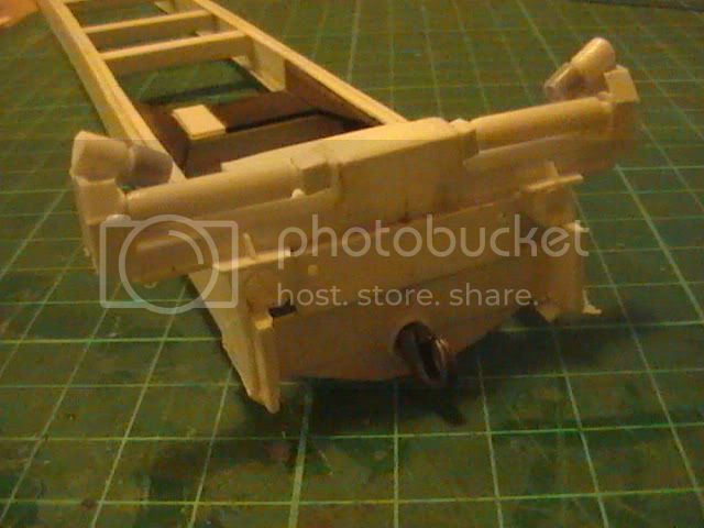
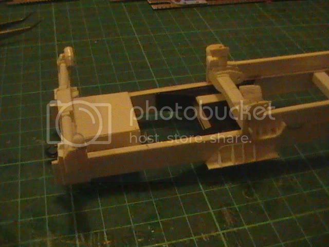
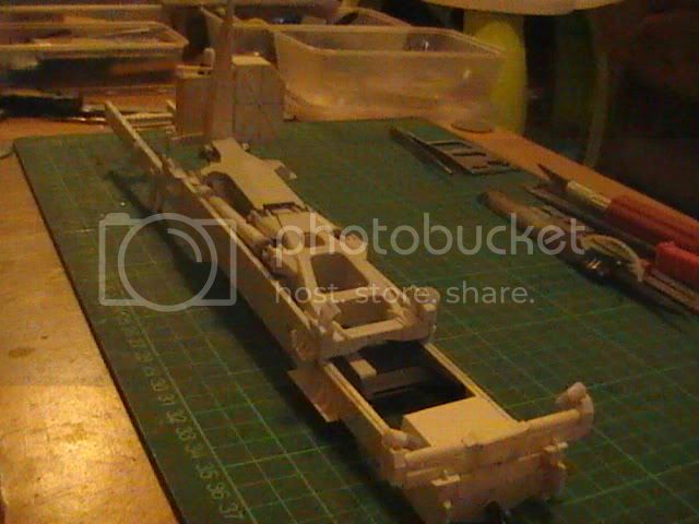
Once formed I drilled the two locations for frame connections and had to make a couple of slight adjustments to the width of the ladder


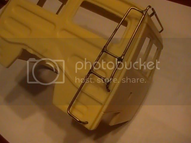
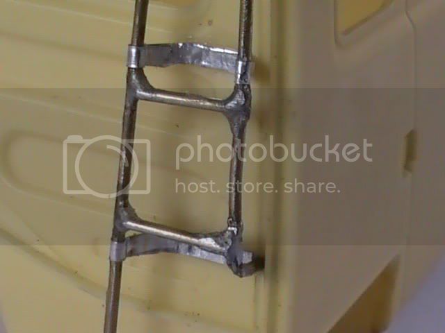
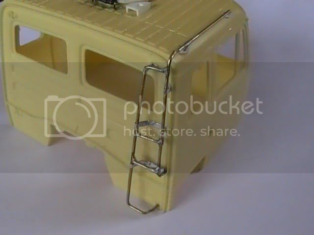
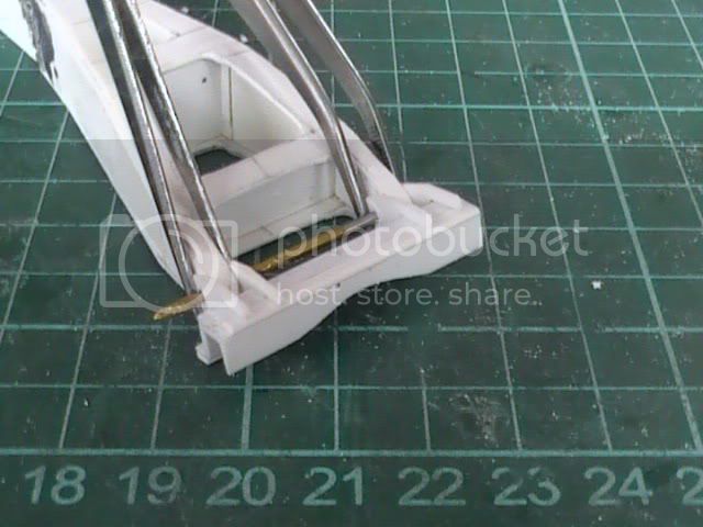
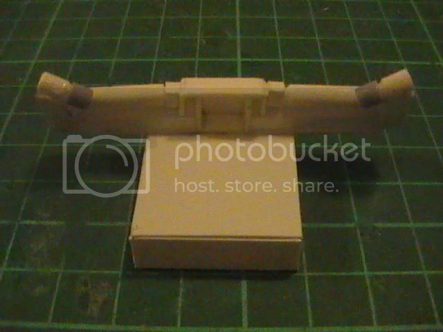
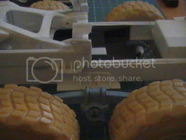
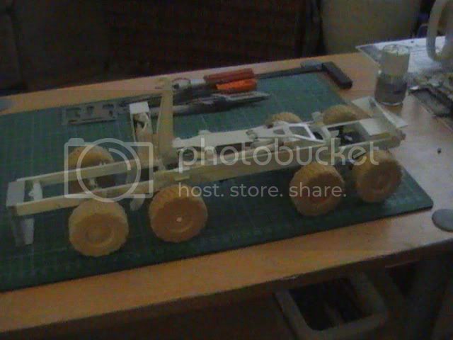
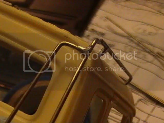
I am more than happy with my first attempt and even without the thinner cab connections I still have to add the ladder is quite secure and very sturdy as is. Still got a little bit of filing of joints to do but hope you like


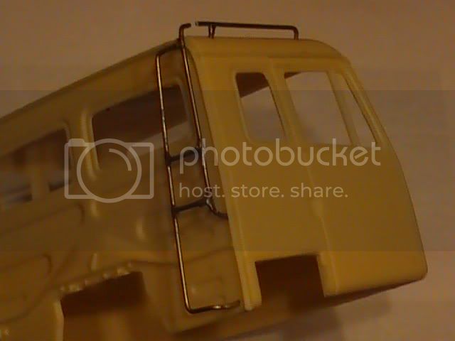
Certainly will be finding more things to use my soldering iron for in future as metal joints are very tough

Nige
okdoky
Visit this Community
Scotland, United Kingdom
Member Since: April 30, 2007
entire network: 1,597 Posts
KitMaker Network: 673 Posts
Posted: Friday, August 13, 2010 - 08:08 AM UTC
Got the lighter brackets on the ladder added using tin foil with bolt fixings of chopped, stretched sprue


added fixing points and their bolt heads to the roof top grab rails


Nige
KoSprueOne
Visit this Community
Myanmar
Member Since: March 05, 2004
entire network: 4,011 Posts
KitMaker Network: 879 Posts
Posted: Wednesday, August 18, 2010 - 12:31 PM UTC
wow, you're really going all the way with this one. I've never tried soldering parts yet.
I was looking through the hydraulic cylinder build up progress because I'll need a few of those on my crane arm as well.


okdoky
Visit this Community
Scotland, United Kingdom
Member Since: April 30, 2007
entire network: 1,597 Posts
KitMaker Network: 673 Posts
Posted: Wednesday, July 27, 2011 - 10:24 AM UTC
I have to make a big shout out to Iain, AKA grousebeater, from IPMS forum for taking the time out to make a couple of disks of much needed photos and information on the DAF to help me kick start the builds.

Met him at Stirling Services on his way back from his DHL run north where he hand delivered the disks and a few other nice bits of info on the new MAN and Wolf. This means I can get a few important reference pics printed off at work so that I can concentrate on important chassis items that, to date, were hidden details that were holding me up.

I would have had to fudge the chassis which is far too open when the flat rack is not mounted. Prop shafts, gear box, transmission, differentials, steering, suspension anti roll bars, brake systems and other useful running gear items are now much clearer now that Iain has taken photos from the maintenance pit.

Very much appreciated Iain and great to have made your acquaintance again after so many years.

Hopefully a KUTA and a resumption of progress on this stalled project.

Cheers

Nige
old-dragon
Visit this Community
Illinois, United States
Member Since: August 30, 2005
entire network: 3,289 Posts
KitMaker Network: 592 Posts
Posted: Wednesday, July 27, 2011 - 10:52 AM UTC
Man Nigel, you rock on this one! Excellent work as always...gotta track down that buss build I thought you were doing- perhaps it will inspire my Greyhound Scenic cruiser build!
Murdo
Visit this Community
Scotland, United Kingdom
Member Since: May 25, 2005
entire network: 2,218 Posts
KitMaker Network: 760 Posts
Posted: Wednesday, July 27, 2011 - 11:11 AM UTC
Excellent stuff Nige!
bigmal
Visit this Community
England - East Midlands, United Kingdom
Member Since: February 21, 2011
entire network: 211 Posts
KitMaker Network: 36 Posts
Posted: Thursday, July 28, 2011 - 07:50 AM UTC
I can now see why progress on the Lightweight stopped.
Superb work, Nige


Malcolm
okdoky
Visit this Community
Scotland, United Kingdom
Member Since: April 30, 2007
entire network: 1,597 Posts
KitMaker Network: 673 Posts
Posted: Thursday, August 11, 2011 - 12:20 PM UTC
Had some time to work on DAF but not had Lappy dongle to put stuff up for view. Will hopefully post some pics soon as Mum in Law arrived at caravan with her lappy and dongle.

Wait ,,,,,,,,,, out !!!!!!!!!

Nige
okdoky
Visit this Community
Scotland, United Kingdom
Member Since: April 30, 2007
entire network: 1,597 Posts
KitMaker Network: 673 Posts
Posted: Friday, August 12, 2011 - 11:08 AM UTC
Normal Service Has Resumed !!!!!!!!!!!! WELL AS NORMAL AS IT EVER GETS WITH ME ANYWAY !!!!!!! Back home early as my dear Dad in hospital. Making use of this time to post pics of progress while I can !!!!!!!

Start of hols at Lossie appeared to offer hope of glorious weather and lots of opportunities to work outside doing some Al-fresco model building.


Was not happy with the main frame in resin as there were inaccuracies with the pivot points that would have bit my bum later in the build if not corrected.


Plasticard cut to shape in three layers with spacers to form the front end and then a top and bottom sheet cut to make the 'A' frame section. A leather hole punch used to cut the rounded internal corners.


Side and internal faces of the 'A' frame help make for a more accurate shape and strong arm


Arron kept a good eye on Daddy to make sure he was doing a better job on the new parts


More to follow
okdoky
Visit this Community
Scotland, United Kingdom
Member Since: April 30, 2007
entire network: 1,597 Posts
KitMaker Network: 673 Posts
Posted: Friday, August 12, 2011 - 11:22 AM UTC
Not happy with the pivot points for the HIAB gear, I chopped this one off and started again


Much improved version with more accurate shape formed using a combination of L , U and simple thin strips of plasticard


New hinges formed by lightly glued plasticard pieces (times four) to form laminated block. Drilling a hole through. Sanding to shape. Then using a sharp blade to de-laminate the four pieces.


Gripping tweezers used to hold the pieces in place in correct location while glue sets


okdoky
Visit this Community
Scotland, United Kingdom
Member Since: April 30, 2007
entire network: 1,597 Posts
KitMaker Network: 673 Posts
Posted: Friday, August 12, 2011 - 11:37 AM UTC
Time to make pivot points on the main arm for the hydraulic rams to act on by laminating strips of card. Drilling, cutting and sanding to shape. Very fiddly but far more accurate and surprisingly strong


These are multi-faceted and were awkward to sand but well worth the effort


okdoky
Visit this Community
Scotland, United Kingdom
Member Since: April 30, 2007
entire network: 1,597 Posts
KitMaker Network: 673 Posts
Posted: Friday, August 12, 2011 - 11:49 AM UTC
HIAB sub frame rear attachment points to the main chassis


Guides and locating lugs that secure the flatrack on the subframe when lifted by the HIAB


okdoky
Visit this Community
Scotland, United Kingdom
Member Since: April 30, 2007
entire network: 1,597 Posts
KitMaker Network: 673 Posts
Posted: Friday, August 12, 2011 - 12:13 PM UTC
Time to work on the running gear now I have some better pics thanks to Grousebeater (Iain)> Much appreciated mate !!!!!!!!!!!!!!!!!!

Second axle (non-driven) with a dropped beam arrangement to allow the prop shafts to pass through


Thick card forms the spine onto which thinner card added to top and bottom to form I section


The ends were laminated all around using thick card to allow a hole to be drilled which can accept aluminum tube to take the wheels


I had misjudged the length of the axles and had to move the lamination further inboard, re-drill and sand to get the correct track width.


okdoky
Visit this Community
Scotland, United Kingdom
Member Since: April 30, 2007
entire network: 1,597 Posts
KitMaker Network: 673 Posts
Posted: Friday, August 12, 2011 - 12:30 PM UTC
Need to make the first (powered) steering axle. Laminated circles of card and added filler


Slightly oversized but will allow for much sanding to shape


Spliced into the axle of laminated strips plastic


The rear (fourth) driven axle has a very similar diff shape to the first axle so were made up at the same time to compare shape. First axle has square section, with third and fourth axle having circular section.


okdoky
Visit this Community
Scotland, United Kingdom
Member Since: April 30, 2007
entire network: 1,597 Posts
KitMaker Network: 673 Posts
Posted: Friday, August 12, 2011 - 12:44 PM UTC
Third axle includes additional housings to accommodate (I PRESUME) low gearing, to transmit power to the rear through it and provide the options for locking diffs, etc.


Well that has got most of the work to date up . Hopefully not the last of progress. Please look at previous posts to see the earlier updates.

Nige
KoSprueOne
Visit this Community
Myanmar
Member Since: March 05, 2004
entire network: 4,011 Posts
KitMaker Network: 879 Posts
Posted: Friday, August 12, 2011 - 05:15 PM UTC
WOW incredible progress indeed, sir


okdoky
Visit this Community
Scotland, United Kingdom
Member Since: April 30, 2007
entire network: 1,597 Posts
KitMaker Network: 673 Posts
Posted: Saturday, August 13, 2011 - 10:33 AM UTC

Quoted Text

WOW incredible progress indeed, sir


Thanks for looking in. Hopefully it is the KUTA I needed to keep progress going !

Nige
okdoky
Visit this Community
Scotland, United Kingdom
Member Since: April 30, 2007
entire network: 1,597 Posts
KitMaker Network: 673 Posts
Posted: Sunday, October 09, 2011 - 04:34 AM UTC
Got a tiny little bit of work added. But it still counts as work for me !!!!!

LHS rear roller assembly


Still have the angled rollers to work out yet but will see if I can add these today too.

Nige
KoSprueOne
Visit this Community
Myanmar
Member Since: March 05, 2004
entire network: 4,011 Posts
KitMaker Network: 879 Posts
Posted: Sunday, October 09, 2011 - 05:14 AM UTC
ok, nice to see this project back in the 'middle' of the bench


okdoky
Visit this Community
Scotland, United Kingdom
Member Since: April 30, 2007
entire network: 1,597 Posts
KitMaker Network: 673 Posts
Posted: Sunday, October 09, 2011 - 08:45 AM UTC

Quoted Text

ok, nice to see this project back in the 'middle' of the bench


Thanks Ko for looking in

A little correction to the main roller lengths and the addition of the guide rollers


Is nice to touch plastic for a change instead of poo bums and plasterboard !!!!! I must promise myself to do this more often.

Nige
AussieReg
Staff MemberAssociate Editor
AUTOMODELER
#007
Visit this Community
Victoria, Australia
Member Since: June 09, 2009
entire network: 8,156 Posts
KitMaker Network: 593 Posts
Posted: Sunday, October 09, 2011 - 03:43 PM UTC
Great work going on here Nige. I have to scratch-build a 1/12th scale tandem trailer next year sometime and you work here is giving me some great ideas.

Cheers, D
okdoky
Visit this Community
Scotland, United Kingdom
Member Since: April 30, 2007
entire network: 1,597 Posts
KitMaker Network: 673 Posts
Posted: Tuesday, October 11, 2011 - 12:11 PM UTC
Added the rear tool locker below the rear rollers


Have got to figure out the correct dimensions for the mounting brackets that connect to the chassis and take the weight of the rollers while loading a flat rack. The box makes use of the space between.

I can't ever remember having to go into the box or what was supposed to be carried in it. Maybe regular soldiers can say what was to be put in the box.

Nige
bigmal
Visit this Community
England - East Midlands, United Kingdom
Member Since: February 21, 2011
entire network: 211 Posts
KitMaker Network: 36 Posts
Posted: Thursday, October 13, 2011 - 05:35 AM UTC
Looking good Nige
How`s the Lightweight?


Malcolm
okdoky
Visit this Community
Scotland, United Kingdom
Member Since: April 30, 2007
entire network: 1,597 Posts
KitMaker Network: 673 Posts
Posted: Saturday, October 22, 2011 - 01:03 PM UTC

Quoted Text

Looking good Nige
How`s the Lightweight?


Malcolm


Hi Malcolm

Lightweight has taken backseat the DAF for the moment as a pall from the TA gave me a heap of info and an offer to get to the TA center to crawl all over one again before they go off line with the army.

A little bit of progress: -

Rear rollers mounted on chassis


A compromise on the leaf spring support brackets as they will have to take a lot of weight from the KFS resin cab


The rear pivot point for the walking suspension pivot points. Also acts as the rear mounting point for the LHS sub frame


Nige
okdoky
Visit this Community
Scotland, United Kingdom
Member Since: April 30, 2007
entire network: 1,597 Posts
KitMaker Network: 673 Posts
Posted: Sunday, October 23, 2011 - 09:35 AM UTC
Hi folks

I need to figure out the best wire or tubing to use for the hydraulic pipes and the best way of making connections that will not be fiddly to put together as sub assemblies, will be flexible enough to accept some movement when posing the LHS, will accept paint whether acrylic or enamel and won't pop out at the slightest knock or vibration.

Any ideas greatly welcome as well as a source if known.

Nige