

Tools & Supplies
Discussions on the latest and greatest tools, glues, and gadgets.
Discussions on the latest and greatest tools, glues, and gadgets.
Hosted by Matt Leese
Build a Tool II "official thread"

matt

Member Since: February 28, 2002
entire network: 5,957 Posts
KitMaker Network: 2,626 Posts
Posted: Thursday, November 27, 2008 - 03:27 PM UTC
Nope...... my but didn't wanna get out of bed....... Building a loft in the Munchkin's room tomorrow.... maybe on Sat I'll be able to!!
Cardshark_14
Member Since: June 24, 2008
entire network: 69 Posts
KitMaker Network: 51 Posts

Posted: Monday, December 01, 2008 - 08:51 PM UTC
Well, now that the Turkey's worn off, I've got some progress... 
Hokay, here we go. By popular demand, a WIP of a safe, large, and portable, spray booth for less than $235.
(Artograph - $235+S/H, Badger - $305 + S/H Paasche - $285+S/H)
I've decided to also build a rolling cart for the spray booth. I will post the cost of materials for that as well, but I won't be counting it towards my cost limit, as it is not comparable to something commercially available.
Materials and Specialty Tools:
Malco sheet metal shears drill attachment $41.00
4' x 8' sheet of 28 gauge sheet metal $35.00
4-1/4" hole saw $35.00
power supply $20.00
fluorescent lights $17.00
grate $15.00
5 x 110 CFM electric brushless computer fans $15.00
butcher paper (12" x 1000') $15.00
furnace filter $8.50
12-1/2" square to 8" round reducer $5.50
8' aluminum flex duct $5.00
lots of rivets $3.00
8" to 6" reducer $3.00
weather stripping tape $3.00
lazy susan $3.00
assorted machine screws $2.50
6" to 4" reducer $2.00
assorted nuts $1.50
2' x 3/4" square aluminum tubing $1.50
rubber grommets $0.50
assorted leftover 2x4s and 4x4s (scrap wood) FREE
TOTAL: $232.00
Tools:
5 assorted c-clamps
tape measure
speed square
pop riveter
drill
basic drill bit set
sharpie permanent marker
large T-square
punch
hammer
hacksaw
2 steel 12" rulers
caulk gun
Initial Plan:
Cut out flattened shape of spray booth. Use hole saw to cut out fan holes. Use clamps, rulers, and large T-square to fold into shape. Use rivets to attach tabs and sides and to connect reducers. Use Machine Screws to attach fans and reducer. Cut 1" pieces of square tubing for filter to rest on. Set grate on filter. Set lazy susan on grate. Wire light and fans to power supply.
I will offload and add step by step pictures, as well as way more information once this thing is complete. If you have any questions, please ask.
Cardshark_14
Member Since: June 24, 2008
entire network: 69 Posts
KitMaker Network: 51 Posts
Posted: Monday, December 01, 2008 - 08:57 PM UTC
Ok, I spent this evening wiring the fluorescent light up, and laying out all my mounting holes, to be drilled once I have access to my friend's garage again (hopefully tomorrow evening). I live in an apartment complex, so most of the work has to be done at a friend's house.
So far, I've spent 12 hours on Sunday, designing, laying out, cutting out, and building the actual booth. All sheet metal work is now done.
Today I put in another 8 hours this evening, acquiring the rest of my materials, assembling the fluorescent light, and laying out all the rest of my mounting holes, to be drilled once I have access to my friend's garage again. I live in an apartment complex, so most of the work has to be done at a friend's house.
Spray Booth 'To Do' List:
*Drill & mount fans to bolt-on assembly
*Drill & mount reducers to bolt-on assembly
*Mount flex duct to bolt-on assembly
*Drill & mount fluorescent light strip
*Drill fan power wire hole in booth
*Drill light power wire hole in booth
*Cut, drill, and mount spacers for filter
*Insert grommets and wire fans and light into power supply
While this finishes the spray booth project itself, I have a rolling spray booth cart to build, as well as setting everything up. Once the spray booth itself is done, I'll post a materials/specialty tools list and costs for the cart.
It is important to both me and SWMBO that we both find our workspaces useful and aesthetically pleasing. So, for the cart's main structure, I went to Office Depot and bought a chrome wire hanging file folder cart.
I plan to mount a nice wood tabletop surface to the top of the cart. It will be made from a piece of plywood left over from a set of workbenches/desks that I made, and stained and tung oiled to match them. The spray booth will then mount on top of that, as well as my air regulator and my airbrush holders. My compressor and airbrush tools and parts will be below the spray booth on the cart.
Spray Booth Cart 'To Do' List:
*Cut and rout an edge on plywood table top
*Remove center section of table top so reducers will pass through
*Stain and tung oil table top
*Use hole saw to create fan wire hole in table top surface
*Use hole saw to create holes for table top surface to mount to cart
*Bolt spacers and spray booth to table top surface
*Mount power strip, power supply, air regulator and airbrush holders to tabletop
*Slide tabletop and spray booth assembly over cart poles
*Set up compressor and airbrush lines
*Cut window vent board to length
*Stain and tung oil window board
*Install dryer vent in window board
*Use the darn thing!!!
Cardshark_14
Member Since: June 24, 2008
entire network: 69 Posts
KitMaker Network: 51 Posts
Posted: Wednesday, December 10, 2008 - 02:30 PM UTC
Ha! Progress! A little at least...Elapsed time: 24 hours
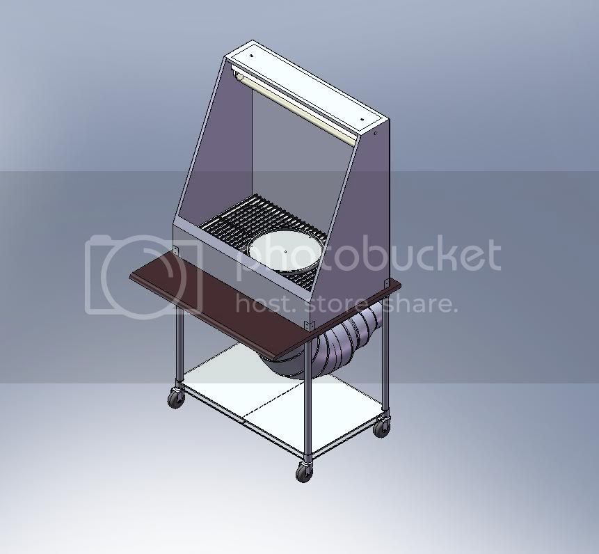
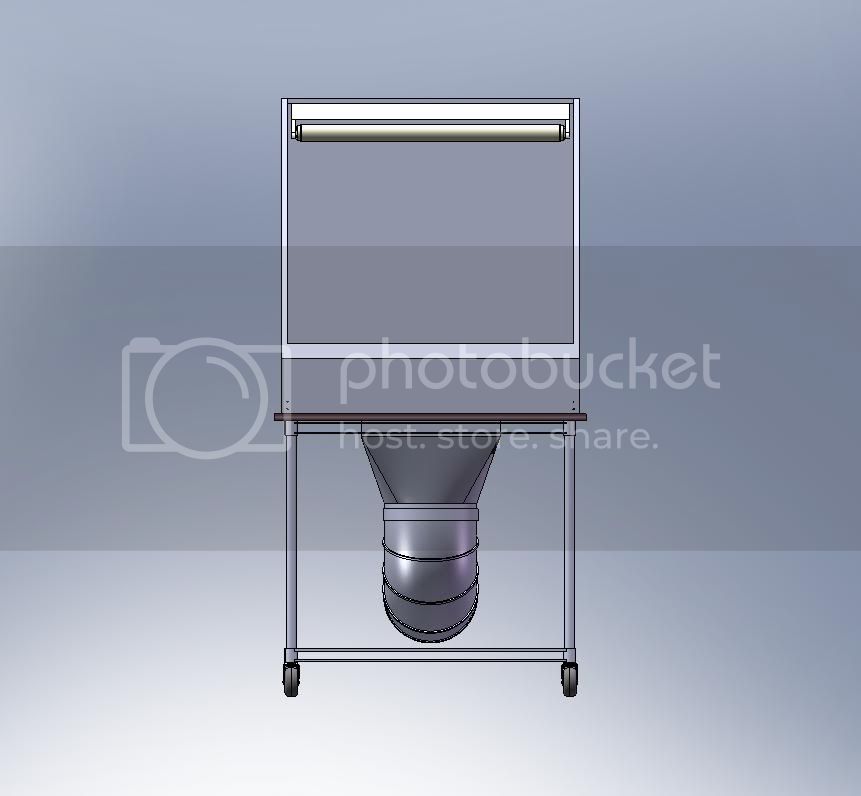
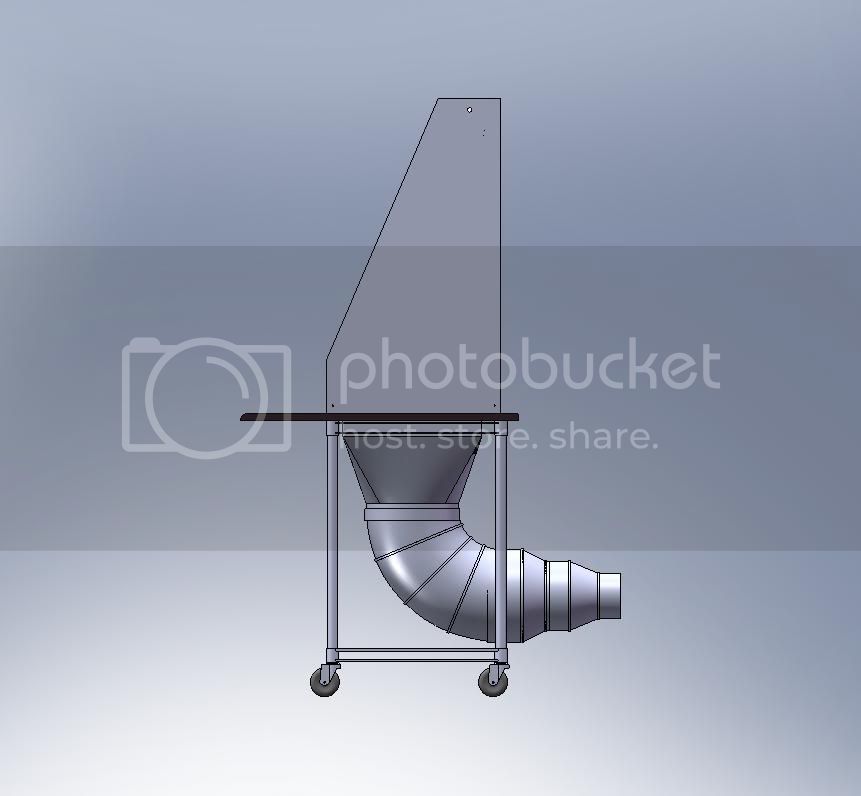
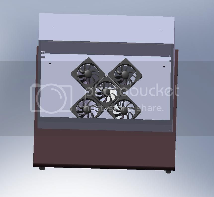
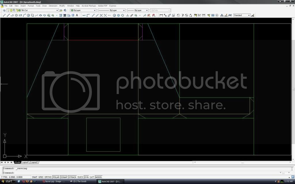
I spent 5 hours today on the project. After some deliberation, I decided to add a plexiglass hinged lid to my design. 1 hour was spent wandering around hardware stores looking for acrylic and possible hinges. Another hour was spent at work over lunch time banging out a quick representation of the finished project in Solid Works, sans plexiglass lid. The other 3 hours were used to mark all my hole centers and cuts, so that when I have access to my friend's garage again (hopefully this Friday night) I can finish this thing. As an appetizer, here are some screenshots from Solid Works:
Isometric view:
Front view:
Side view:
Fan and vent detail:
Kinda quiet on here, anybody else got a tool in progress?
Silantra

Member Since: March 04, 2004
entire network: 2,511 Posts
KitMaker Network: 1,296 Posts

Posted: Wednesday, December 10, 2008 - 04:24 PM UTC
Now i'm in the process of makign my new spray booth.
Most major stuff are gathered
Just got a new 165 CFM fan...
and last week i bought some wood and plywoods, and went to garbage disposal site for some glass and acrylics sheets.... hehehe.. have to be economical this time... bought soem electrical stuff for the light and wiring ...
must get it done this weekend
on paper, i had ptu a few design according to ACGIH and following ANSI standard as well..not the material but the efficiency of the suction....
hope i got all the time....
Cardshark_14
Member Since: June 24, 2008
entire network: 69 Posts
KitMaker Network: 51 Posts
Posted: Sunday, December 14, 2008 - 11:00 AM UTC
I've just gotten the all clear to go finish this thing at my friend's house. Hopefully it'll be done later tonight. Stay tuned!
Cardshark_14
Member Since: June 24, 2008
entire network: 69 Posts
KitMaker Network: 51 Posts
Posted: Monday, December 15, 2008 - 08:40 AM UTC
I put in another 6 1/2 hours on Sunday, and the whole thing's almost done, I need to caulk the joints and attach the plexiglass lid and hinges, but that can be done at any time. I can start using it really soon! Hooray! 
Total Elapsed Time: 30 1/2 hours
I apologize in advance for dropping into technical writing/ME report mode.
From the start...
I started with a piece of 28 gauge sheet metal, and marked out the spray booth unfolded on it using a Sharpie.
Next, the flattened shape was cut out using this attachment:
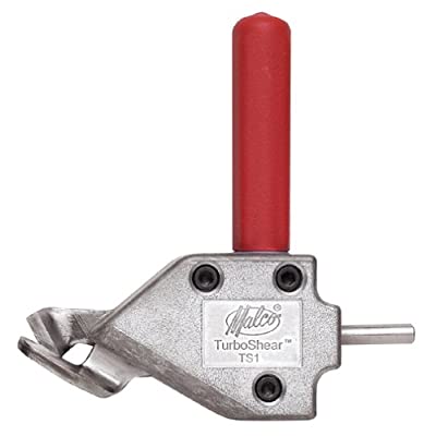
The shank of the attachment goes into any drill, and the internal gearbox converts rotary motion into a vertical snipping motion. I was a bit leery of using something like this as it seemed a bit hokey, but it goes through 28 gauge like a hot knife through butter.
A 3/8" drill bit was used to open up a hole to insert the shears to cut out the square in the bottom of the spray booth where the fan and reducer assembly would eventually go.
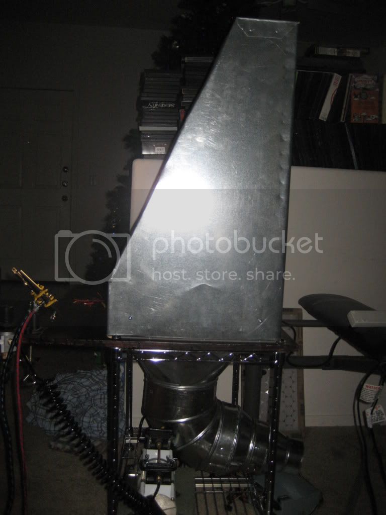
Lacking a brake, I had to get creative. I wanted stress bends on the back, as it was a large, flimsy expanse of metal with no real rigidity. My friend's garage has a cement floor with expansion joints about 1/4" wide. I laid the sheet metal over the expansion joint, and held a 4x4 with just the corner touching and smacked it with a hammer to imprint a stress bend in the metal. I rotated the sheet metal 180 degrees and repeated the work. This formed the familiar X shape ribs found on large ductwork, similar to what is shown below.

Using clamps and steel rulers to spread the force evenly, the tabs and sides of the spray booth were folded. Sharp 90 degree folds were made by holding a scrap piece of 4x4 on the inside of the fold, and hitting the outside of the fold with a hammer. After everything was folded, clamps were used to hold parts together, while 1/8" holes were drilled. The tabs were then riveted in place.
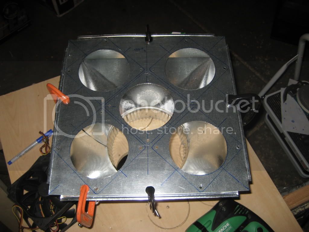
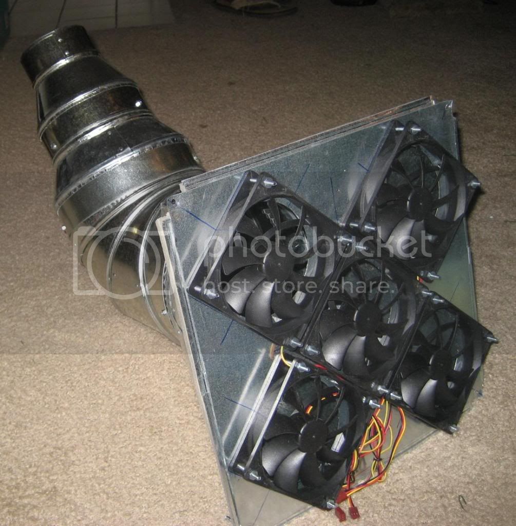
Next, the fan and reducer assembly was built. First, a leftover piece of sheet metal 12 3/4" on a side was cut out. Five 4 1/8" holes were marked out, and drilled out using a hole saw. The fans were then clamped in place and their mounting holes were drilled out as well. The fans were then mounted to the metal using machine screws in all holes except those along the outer edge. The square reducer's mounting flanges were pulled off, and slits were cut so that new mounting tabs that would sit flush could be bent out. The fan assembly was then clamped to the reducer flanges, and the outer fan mount holes were chased out through the reducer.
Next, the other reducers were were attached using self-tapping sheet metal screws. the joints were then wrapped in foil tape. Finally, weatherstripping was applied to the bottom of the reducer flange, the assembly was held in place, holes were drilled in the corners, and machine screws were used to mount the whole thing. The sheet metal work was now complete.
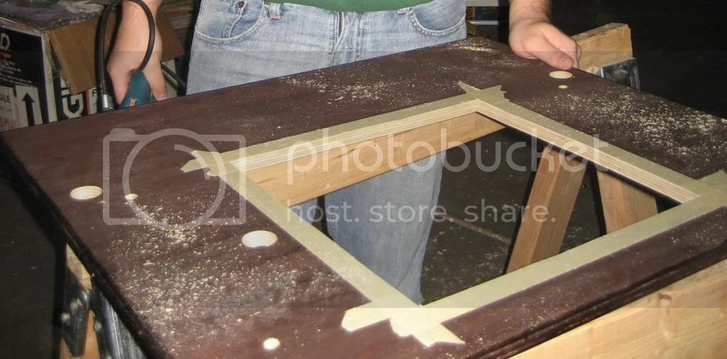
Next, the tabletop was cut to size, routed, and stained. Locations for the connecting bolts and the cart posts were then covered in masking tape to prevent splintering, marked out on the bottom, and drilled. A 3/8" drill bit was once again used to provide a starting hole for a jigsaw to cut out the square shapewhere the fan and reducer assembly would eventually go. A line of weatherstripping was laid out to form a tight seal between the bottom of the spray booth, the rivets, and the table top.
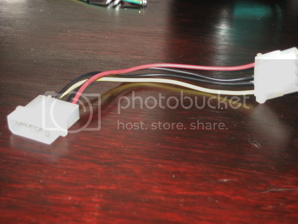
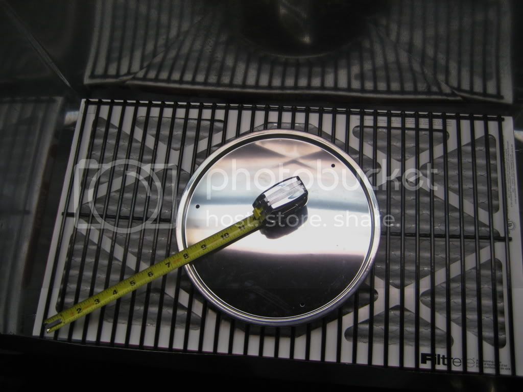
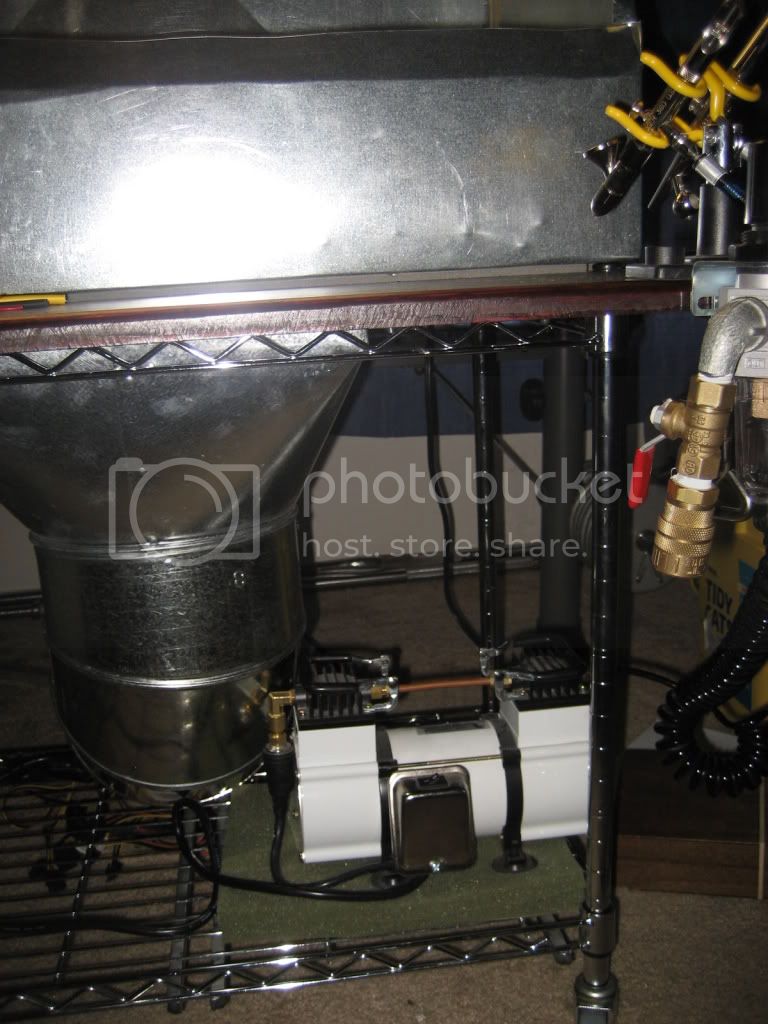
Major assembly was now done, and we started on odds and ends. With the tabletop complete, we clamped the spray booth in place, and chased out holes in the bottom of it for the connecting bolts, which were then bolted down, and the fan power wire. A grommet was inserted into the fan power wire hole. Holes were also drilled in the top of the spray booth to mount the fluorescent light, and it was then mounted. A hole was drilled in the side of the spray booth for the light power wire, and the light was then wired up. The aluminum spacers proved to be disappointing, so we used long machine screws as studs to rest the filter and grate on. The fan wires were attached in parallel, heat shrink-wrappped, sealed, and fed through the power wire hole. Next, they were wired into a quick disconnect, with the other side of the disconnect feeding into the power supply.
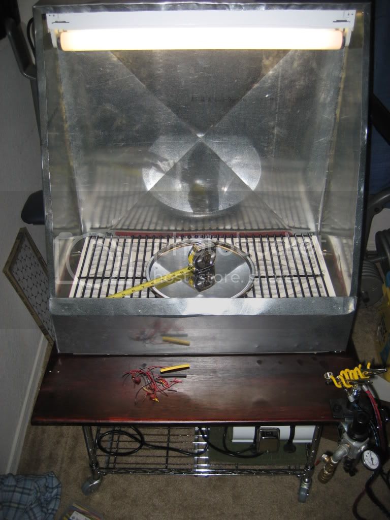
The whole assembly was then slid onto the cart poles, and large washers were used as spacers. Metal straps were screwed into the bottom of the tabletop, and thread through the cart sides to hold the assembly in place. My airbrush regulator, holder, and quick-disconnect were added to the front of the tabletop, while the compressor and power supply were mounted to the bottom of the cart. A power strip was mounted to the bottom of the tabletop, and the power supply, compressor, and lights were plugged in. The filter and grate were placed on their improved supports, and we called it a night!
Feel free to ask any questions you can think of...I'd love to hear your comments and friendly criticism too!
Total Elapsed Time: 30 1/2 hours
I apologize in advance for dropping into technical writing/ME report mode.
From the start...
I started with a piece of 28 gauge sheet metal, and marked out the spray booth unfolded on it using a Sharpie.
Next, the flattened shape was cut out using this attachment:
The shank of the attachment goes into any drill, and the internal gearbox converts rotary motion into a vertical snipping motion. I was a bit leery of using something like this as it seemed a bit hokey, but it goes through 28 gauge like a hot knife through butter.
A 3/8" drill bit was used to open up a hole to insert the shears to cut out the square in the bottom of the spray booth where the fan and reducer assembly would eventually go.
Lacking a brake, I had to get creative. I wanted stress bends on the back, as it was a large, flimsy expanse of metal with no real rigidity. My friend's garage has a cement floor with expansion joints about 1/4" wide. I laid the sheet metal over the expansion joint, and held a 4x4 with just the corner touching and smacked it with a hammer to imprint a stress bend in the metal. I rotated the sheet metal 180 degrees and repeated the work. This formed the familiar X shape ribs found on large ductwork, similar to what is shown below.
Using clamps and steel rulers to spread the force evenly, the tabs and sides of the spray booth were folded. Sharp 90 degree folds were made by holding a scrap piece of 4x4 on the inside of the fold, and hitting the outside of the fold with a hammer. After everything was folded, clamps were used to hold parts together, while 1/8" holes were drilled. The tabs were then riveted in place.
Next, the fan and reducer assembly was built. First, a leftover piece of sheet metal 12 3/4" on a side was cut out. Five 4 1/8" holes were marked out, and drilled out using a hole saw. The fans were then clamped in place and their mounting holes were drilled out as well. The fans were then mounted to the metal using machine screws in all holes except those along the outer edge. The square reducer's mounting flanges were pulled off, and slits were cut so that new mounting tabs that would sit flush could be bent out. The fan assembly was then clamped to the reducer flanges, and the outer fan mount holes were chased out through the reducer.
Next, the other reducers were were attached using self-tapping sheet metal screws. the joints were then wrapped in foil tape. Finally, weatherstripping was applied to the bottom of the reducer flange, the assembly was held in place, holes were drilled in the corners, and machine screws were used to mount the whole thing. The sheet metal work was now complete.
Next, the tabletop was cut to size, routed, and stained. Locations for the connecting bolts and the cart posts were then covered in masking tape to prevent splintering, marked out on the bottom, and drilled. A 3/8" drill bit was once again used to provide a starting hole for a jigsaw to cut out the square shapewhere the fan and reducer assembly would eventually go. A line of weatherstripping was laid out to form a tight seal between the bottom of the spray booth, the rivets, and the table top.
Major assembly was now done, and we started on odds and ends. With the tabletop complete, we clamped the spray booth in place, and chased out holes in the bottom of it for the connecting bolts, which were then bolted down, and the fan power wire. A grommet was inserted into the fan power wire hole. Holes were also drilled in the top of the spray booth to mount the fluorescent light, and it was then mounted. A hole was drilled in the side of the spray booth for the light power wire, and the light was then wired up. The aluminum spacers proved to be disappointing, so we used long machine screws as studs to rest the filter and grate on. The fan wires were attached in parallel, heat shrink-wrappped, sealed, and fed through the power wire hole. Next, they were wired into a quick disconnect, with the other side of the disconnect feeding into the power supply.
The whole assembly was then slid onto the cart poles, and large washers were used as spacers. Metal straps were screwed into the bottom of the tabletop, and thread through the cart sides to hold the assembly in place. My airbrush regulator, holder, and quick-disconnect were added to the front of the tabletop, while the compressor and power supply were mounted to the bottom of the cart. A power strip was mounted to the bottom of the tabletop, and the power supply, compressor, and lights were plugged in. The filter and grate were placed on their improved supports, and we called it a night!
Feel free to ask any questions you can think of...I'd love to hear your comments and friendly criticism too!
matt
Member Since: February 28, 2002
entire network: 5,957 Posts
KitMaker Network: 2,626 Posts
Posted: Monday, December 15, 2008 - 03:11 PM UTC
Very Nice!!!!! Considering Mine's Plexiglass some preformed duct pieces hot melt glue and Duct tape....... but it works!!!
Cardshark_14
Member Since: June 24, 2008
entire network: 69 Posts
KitMaker Network: 51 Posts
Posted: Tuesday, December 16, 2008 - 06:22 PM UTC
Thanks for the kind words, Matt. I'm working on a way to measure airflow at the outlet, and once I do, I'll let you all know how it does. Thanks for letting me be part of Build a Tool II.
Cheers,
Alex
Cheers,
Alex
Silantra
Member Since: March 04, 2004
entire network: 2,511 Posts
KitMaker Network: 1,296 Posts
Posted: Tuesday, December 16, 2008 - 07:14 PM UTC
Quoted Text
Thanks for the kind words, Matt. I'm working on a way to measure airflow at the outlet, and once I do, I'll let you all know how it does. Thanks for letting me be part of Build a Tool II.
Cheers,
Alex
Alex,
you can use a few equipment for that. Either airflow meter or anemometer.
FYI, measuring the airflow of the outlet doesnt help. What's important is to measure the face velocity (the velocity or air flow rate) at the face of the hood.
and then compare to the standard (if u care about industrial standard). There are a few standard from ANSI you can refer to or just refer to ACGIH (American Conference of Govt Industrial Hygienist ) .. according to ACGIH, the face velocity should be 75 -125 fpm.
btw, that was a huge booth and a neat electrical and plumbing works.... keep it up
I still in the process of getting my time to build....
will ask matt for extension
Cardshark_14
Member Since: June 24, 2008
entire network: 69 Posts
KitMaker Network: 51 Posts
Posted: Tuesday, December 16, 2008 - 08:43 PM UTC
Hi Silantra,
Thanks for your thoughts. I have built my spray booth to ANSI standards, and have calculated an overall theoretical max flow rate of 510 CFM at the face. I have also found a value for the head loss caused by my ductwork. I am interested in obtaining a real world value for both face and outlet velocity, so I can compare to my theoreticals. I don't have access to an anemometer or flow meter at the moment, so I will have to make do without a proper tool. I have a few ways to go about doing this, and when I have the numbers I'll let you all know.
I'm looking forward to seeing your ideas for a booth as well. Keep at it, and let us know how it turns out!
matt
Member Since: February 28, 2002
entire network: 5,957 Posts
KitMaker Network: 2,626 Posts
Posted: Wednesday, December 17, 2008 - 01:53 AM UTC
Anyone needing an extension let me know!!!!
Cardshark_14
Member Since: June 24, 2008
entire network: 69 Posts
KitMaker Network: 51 Posts
Posted: Wednesday, December 17, 2008 - 10:15 AM UTC
Hey Matt,
When does Build A Tool II end? I have some other ideas for stuff to build, but I don't know when I will have the time to get to them.
Cheers,
Alex
When does Build A Tool II end? I have some other ideas for stuff to build, but I don't know when I will have the time to get to them.
Cheers,
Alex

TacFireGuru
Member Since: December 25, 2004
entire network: 3,770 Posts
KitMaker Network: 747 Posts

Posted: Wednesday, December 17, 2008 - 01:23 PM UTC
Quoted Text
When does Build A Tool II end?
Alex, at the moment, it ends December 31, 2008. I have a feeling there will be a "Build a Tool III" down the road. This one is pretty popular and, more importantly (IMO), creative.
Mike


HARV

#012
Member Since: November 07, 2003
entire network: 3,098 Posts
KitMaker Network: 899 Posts
Posted: Wednesday, December 17, 2008 - 01:24 PM UTC
Quoted Text
Anyone needing an extension let me know!!!!
Thanks but am hoping that I don't have to ask for one. I have two real simple hand made tool projects that I want to do and I could do them both in an hour, if I had all of the supplies!! I am just having trouble with my time lately. I am keeping my fingers crossed that I can get them done this weekend. They are simple things like I built for the last campaign. Just poor time management I guess.
HARV


Cardshark_14
Member Since: June 24, 2008
entire network: 69 Posts
KitMaker Network: 51 Posts
Posted: Wednesday, December 17, 2008 - 02:52 PM UTC
Quoted Text
Quoted TextWhen does Build A Tool II end?
Alex, at the moment, it ends December 31, 2008. I have a feeling there will be a "Build a Tool III" down the road. This one is pretty popular and, more importantly (IMO), creative.
Mike
Well, I'll probably hold off until Build a Tool III for more projects since who knows when I'll get to them.
Silantra
Member Since: March 04, 2004
entire network: 2,511 Posts
KitMaker Network: 1,296 Posts
Posted: Wednesday, December 17, 2008 - 03:37 PM UTC
Quoted Text
Hi Silantra,
Thanks for your thoughts. I have built my spray booth to ANSI standards, and have calculated an overall theoretical max flow rate of 510 CFM at the face. I have also found a value for the head loss caused by my ductwork. I am interested in obtaining a real world value for both face and outlet velocity, so I can compare to my theoreticals. I don't have access to an anemometer or flow meter at the moment, so I will have to make do without a proper tool. I have a few ways to go about doing this, and when I have the numbers I'll let you all know.
I'm looking forward to seeing your ideas for a booth as well. Keep at it, and let us know how it turns out!
Alex,
Theoretically, i calculated the design value for all required parameters.
Basically i just used the Q=vA equation and from the fan value i can work with the dimension of the hood... it's a simplified equation and i omitted to many factors. I guess it will be alright. I dont take duct work loss at all..
Last week i put the fan onto a few boxes with different dimension and measure the face velocity and the transport velocity... i guess i cannot build a big booth since the fan limit it..i only got 165 CFM fan....
but the velocity of the duct outlet (flexible aluminium duct) was amazing... more than 1000 fpm which is greater than ANSI Z.x and even ACGIH...
Alex, 510 CFM (or izit FPM) at the face is really big.... i guess multiplying the fan in parallel do work in this case.... mine was about 100 fpm from the center of the booth...
tell me if you need to ask about measurement. I was so lucky that working in DOSH i got access to many monitoring and inspection equipment.
The thing i dont have is time and right now the we got a heavy rain season so i cant work outside..
thanks goodness matt had granted me an extension...
my material of choice is just wood and glass that i found at scrap yard... probably will get some perspex for the front cover...
Good luck all...

HunterCottage

#116

Member Since: December 19, 2001
entire network: 1,717 Posts
KitMaker Network: 590 Posts
Posted: Saturday, December 20, 2008 - 12:56 AM UTC
Although a late-comer I thought I would add my entry. We moved two years ago into a bigger home. Now that most of the other (more important) things are done, I sectioned off a part of the garage for a work area. When the shelving is put in place two people should be able to work here without too much problem...


matt
Member Since: February 28, 2002
entire network: 5,957 Posts
KitMaker Network: 2,626 Posts
Posted: Wednesday, December 24, 2008 - 07:50 AM UTC
tting down to the end guys... If ya need an extension Just ask....... and be sure to officially enter. I'll be working on the ribbon over the weekend..
HARV
#012
Member Since: November 07, 2003
entire network: 3,098 Posts
KitMaker Network: 899 Posts
Posted: Thursday, December 25, 2008 - 05:36 AM UTC
Merry Christmas
I will try to post the photos of my projects when I get home. I tried to the other night but was having some problems.
Should be able to have them done sometime this evening anyway.
HARV
I will try to post the photos of my projects when I get home. I tried to the other night but was having some problems.
Should be able to have them done sometime this evening anyway.
HARV
Silantra
Member Since: March 04, 2004
entire network: 2,511 Posts
KitMaker Network: 1,296 Posts
Posted: Thursday, December 25, 2008 - 06:58 PM UTC
I still havent start anything yet. Just purchased casign for the downlight inside the booth
HARV
#012
Member Since: November 07, 2003
entire network: 3,098 Posts
KitMaker Network: 899 Posts
Posted: Friday, December 26, 2008 - 12:11 PM UTC
Well here are my entries. Nothing too fancy but they are functional.
The first set is a set of clamps that I made with paper clamps and rubber bands. I simply cut the rubber bands in half and then used epoxy to glue one end of the rubber band inside the clamp.

All you have to do is wrap the rubber band around whatever you want held together and then clamp the loose end of the rubber band to hold it tight.

The second set is a set of clamps made with clothes pins and plastic card. I simply cut some different sizes of plastic card and then used epoxy to glue them to the clothes pin.

Then all you do is obviously open the clamp and place what you want held together inside the clamp and then close the clamp.

Not too exciting but both sets are very easy to build and as I mentioned they are functional. I like to make very basic tools with materials that I have on hand. Since the start of the Build-A-Tool campaigns I find myself looking at ordinary household items differently. You never know what you can build a tool with.
I have other ideas for some tools but I am saving them for Build-A-Tool III, IV, V, VI, and beyond!!
Thanks for the campaign Matt. I enjoyed it just as much as I did the first one. Everyone had nice projects that they entered. Good work everyone.
HARV
The first set is a set of clamps that I made with paper clamps and rubber bands. I simply cut the rubber bands in half and then used epoxy to glue one end of the rubber band inside the clamp.
All you have to do is wrap the rubber band around whatever you want held together and then clamp the loose end of the rubber band to hold it tight.
The second set is a set of clamps made with clothes pins and plastic card. I simply cut some different sizes of plastic card and then used epoxy to glue them to the clothes pin.
Then all you do is obviously open the clamp and place what you want held together inside the clamp and then close the clamp.
Not too exciting but both sets are very easy to build and as I mentioned they are functional. I like to make very basic tools with materials that I have on hand. Since the start of the Build-A-Tool campaigns I find myself looking at ordinary household items differently. You never know what you can build a tool with.
I have other ideas for some tools but I am saving them for Build-A-Tool III, IV, V, VI, and beyond!!
Thanks for the campaign Matt. I enjoyed it just as much as I did the first one. Everyone had nice projects that they entered. Good work everyone.
HARV

goldenpony

Member Since: July 03, 2007
entire network: 3,529 Posts
KitMaker Network: 422 Posts

Posted: Monday, December 29, 2008 - 02:31 AM UTC
Quoted Text
Anyone needing an extension let me know!!!!
I would ask for one, but it is still not going to help. I just cannot seem to get time to do much if anything as of late. Plus I put things off until the end and just cannot hope to get everything done.
Like have been mentioned, a BAT III might be in the future, I will hold off until then.
Maybe this could start 1/1/09 since there seems to be an effort asking for it.

matt
Member Since: February 28, 2002
entire network: 5,957 Posts
KitMaker Network: 2,626 Posts
Posted: Monday, December 29, 2008 - 03:22 AM UTC
I have a feeling there will be another......

c5flies
Member Since: October 21, 2007
entire network: 3,684 Posts
KitMaker Network: 411 Posts
Posted: Tuesday, December 30, 2008 - 03:54 PM UTC
Great entries, Harv, I love simple, functional, ingenious things like this! Thanks for the clamps......once I make them that is

 |

WEB HOSTING BY


Copyright ©2021 KitMaker Network and Kitmaker Network, a subsidiary of Silver Star Enterprises
All Rights Reserved. Please read our Conditions of Use and Privacy Policy.
All Rights Reserved. Please read our Conditions of Use and Privacy Policy.