

Modeling in General
General discussions about modeling topics.
General discussions about modeling topics.
Hosted by Jim Starkweather
Abrams help

iowabrit

Member Since: November 06, 2007
entire network: 585 Posts
KitMaker Network: 18 Posts

Posted: Tuesday, November 19, 2013 - 10:28 AM UTC
Many photos of M1's show a spare road wheel and/or sprocket ring on the turret top sitting in front of the loaders hatch. I've searched high and low for a picture showing how these are held in place (presumably by bolts?) but without success. Does anyone have a clear pic from above or a close up of that area of the vehicle without a wheel there?

majjanelson
Member Since: December 14, 2006
entire network: 1,355 Posts
KitMaker Network: 336 Posts
Posted: Tuesday, November 19, 2013 - 03:15 PM UTC
Steve,
The following images from Prime Portal hopefully will answer your questions:
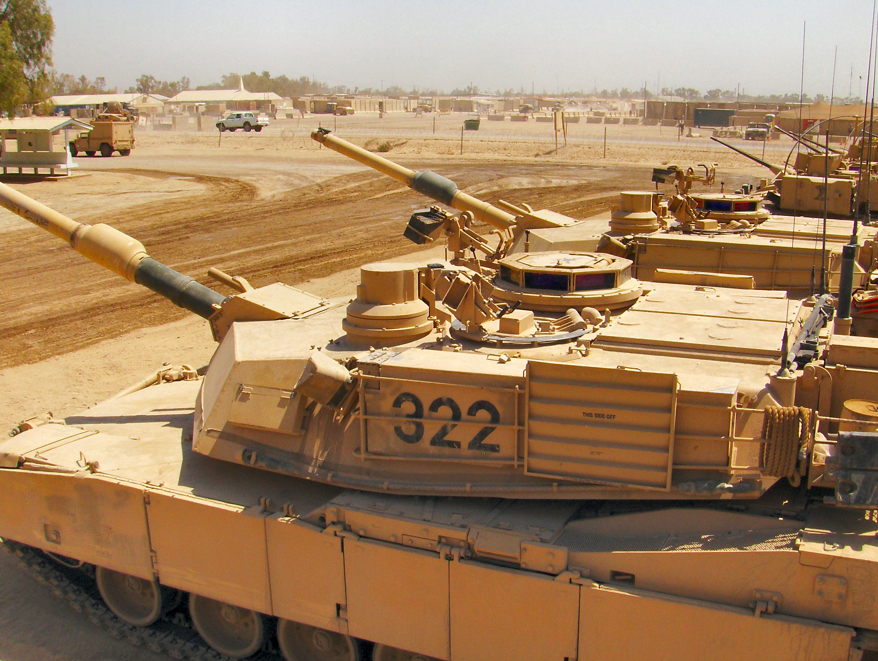
This image shows a M1A1 with a spare road wheel mounted on the "man-hole cover" in front of the Loader's Hatch:
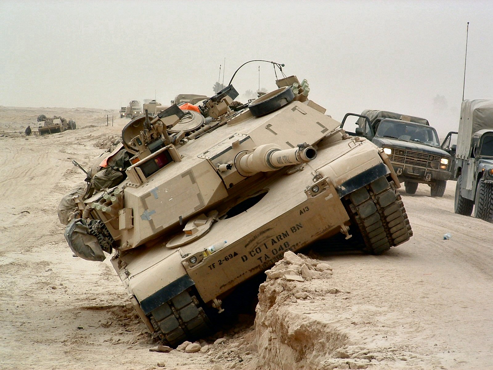
There are three threaded bosses or welded on hex nuts on the cover top that allow one or two bolts to hole a spare road wheel or drive sprocket in place.
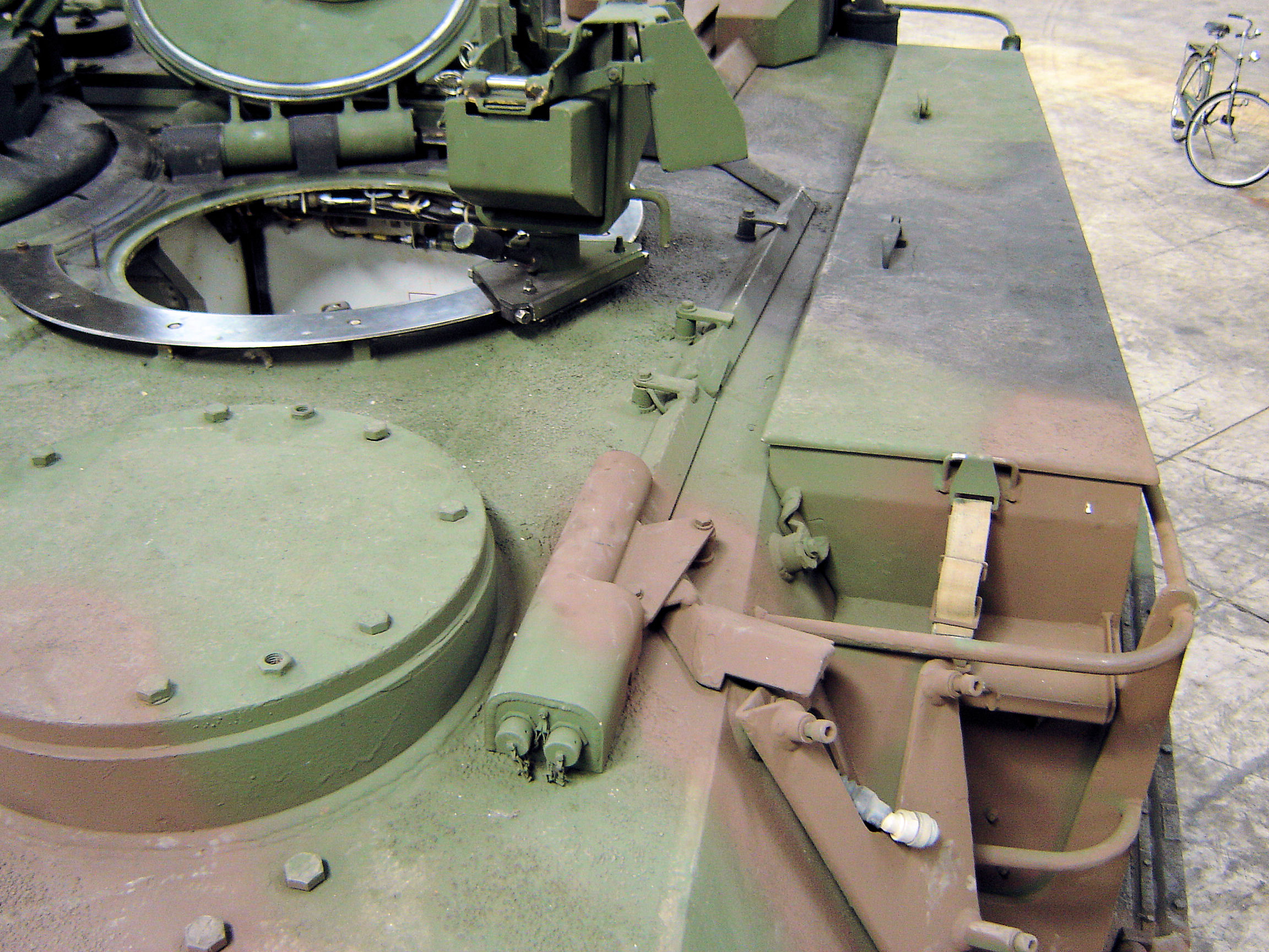
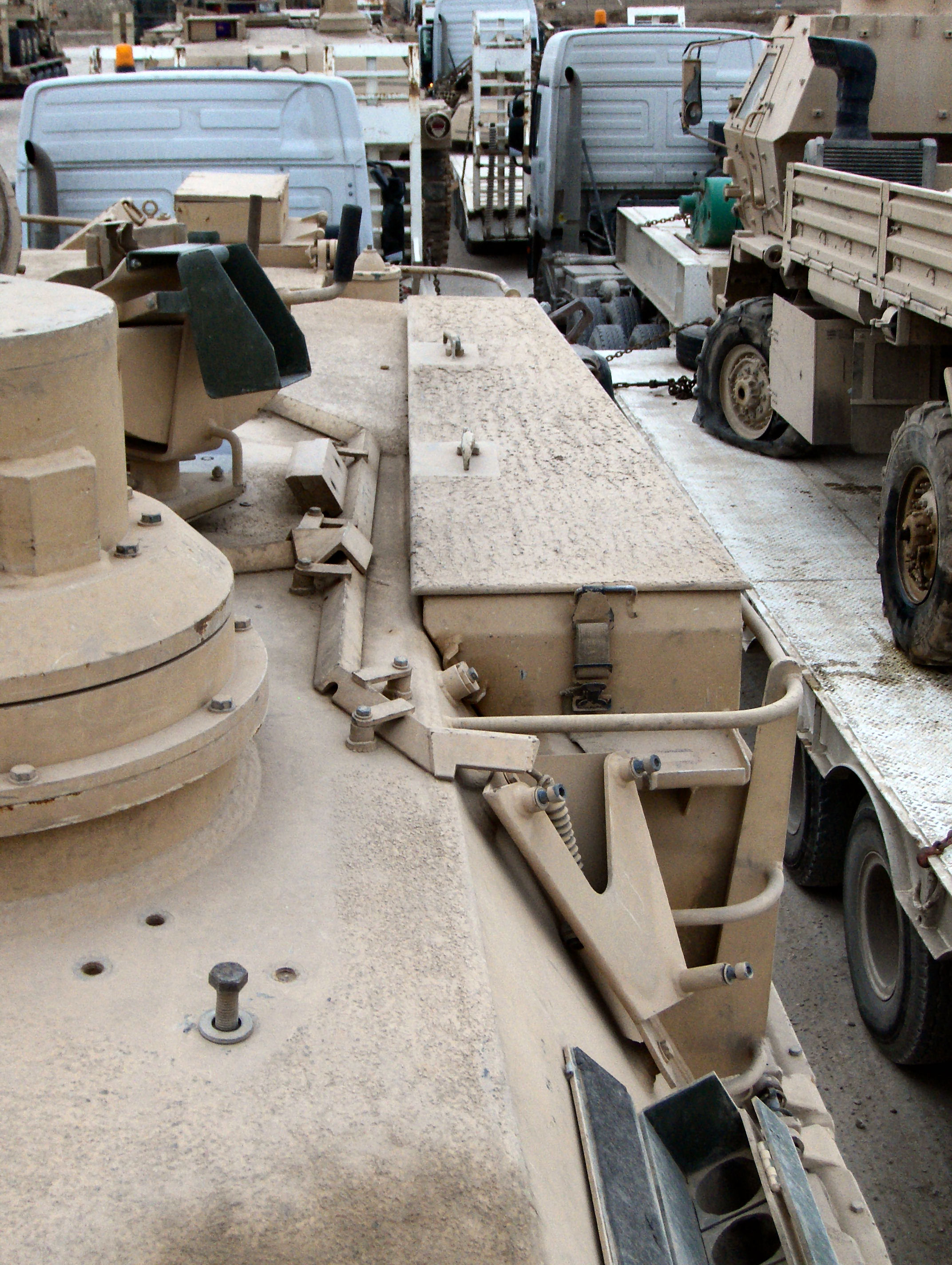
A close up of a spare road wheel in place. Note the 4 bolt heads in front of the "man-hole cover". These are for mounting lifting brackets to lift the turret from the hull.
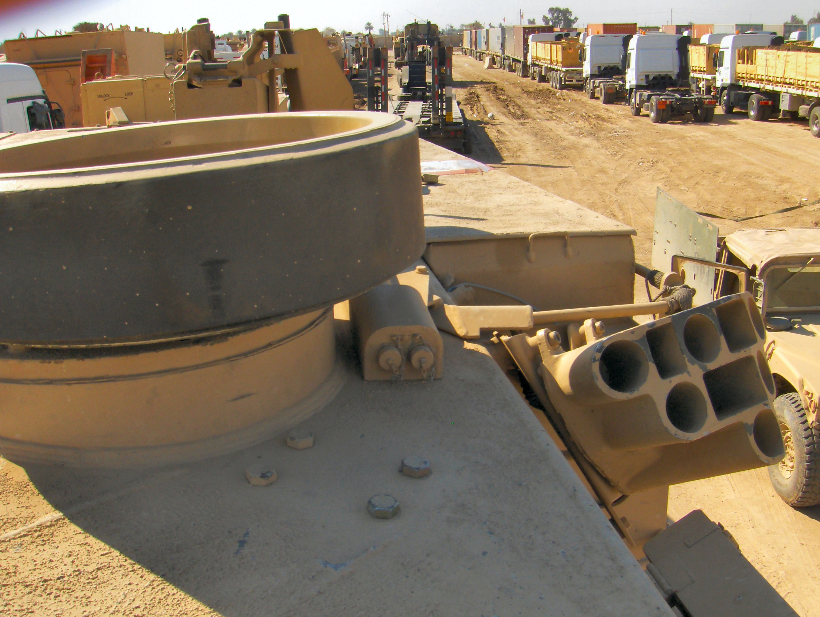
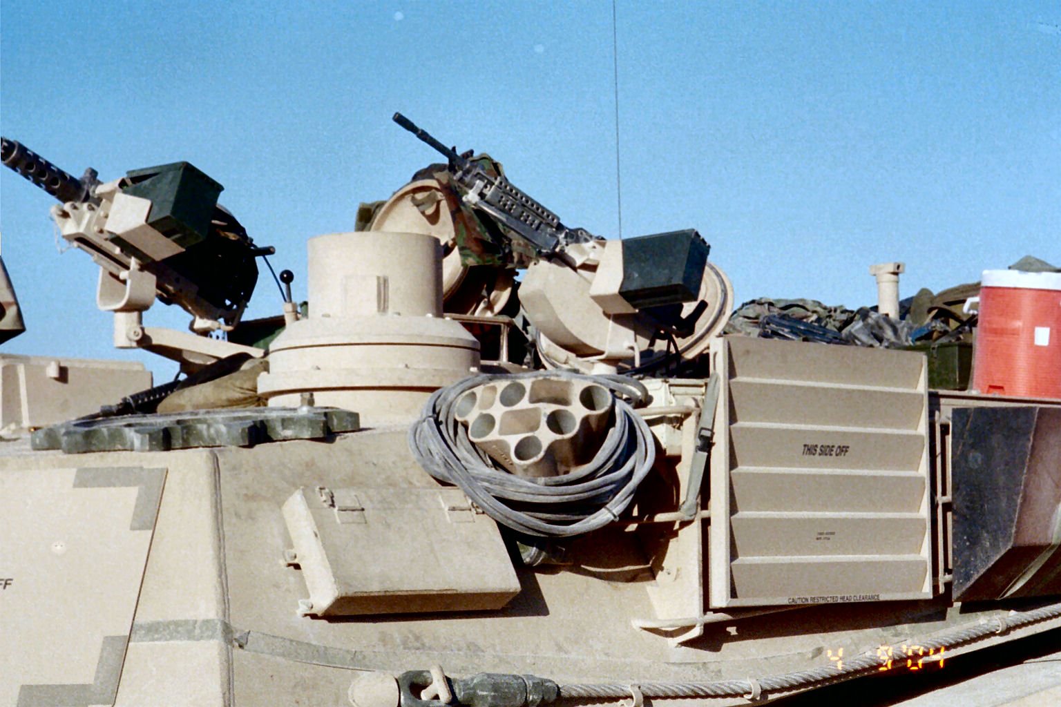
For M1A2s, the "man-hole cover" has a the Commander's Independent Thermal Viewer (CITV) installed so 1 or 2 of the lifting bracket bolts are used instead:
This view shows the 4 bolts just to the left of the CITV:
This image shows 3 bolts removed and 1 loose, likely for installing a spare road wheel or drive sprocket:
This image from the web is of a M1A1 prototype which has a M1 turret without the "man-hole cover" and shows the 4 bolts for the lifting brackets on each side of the turret:

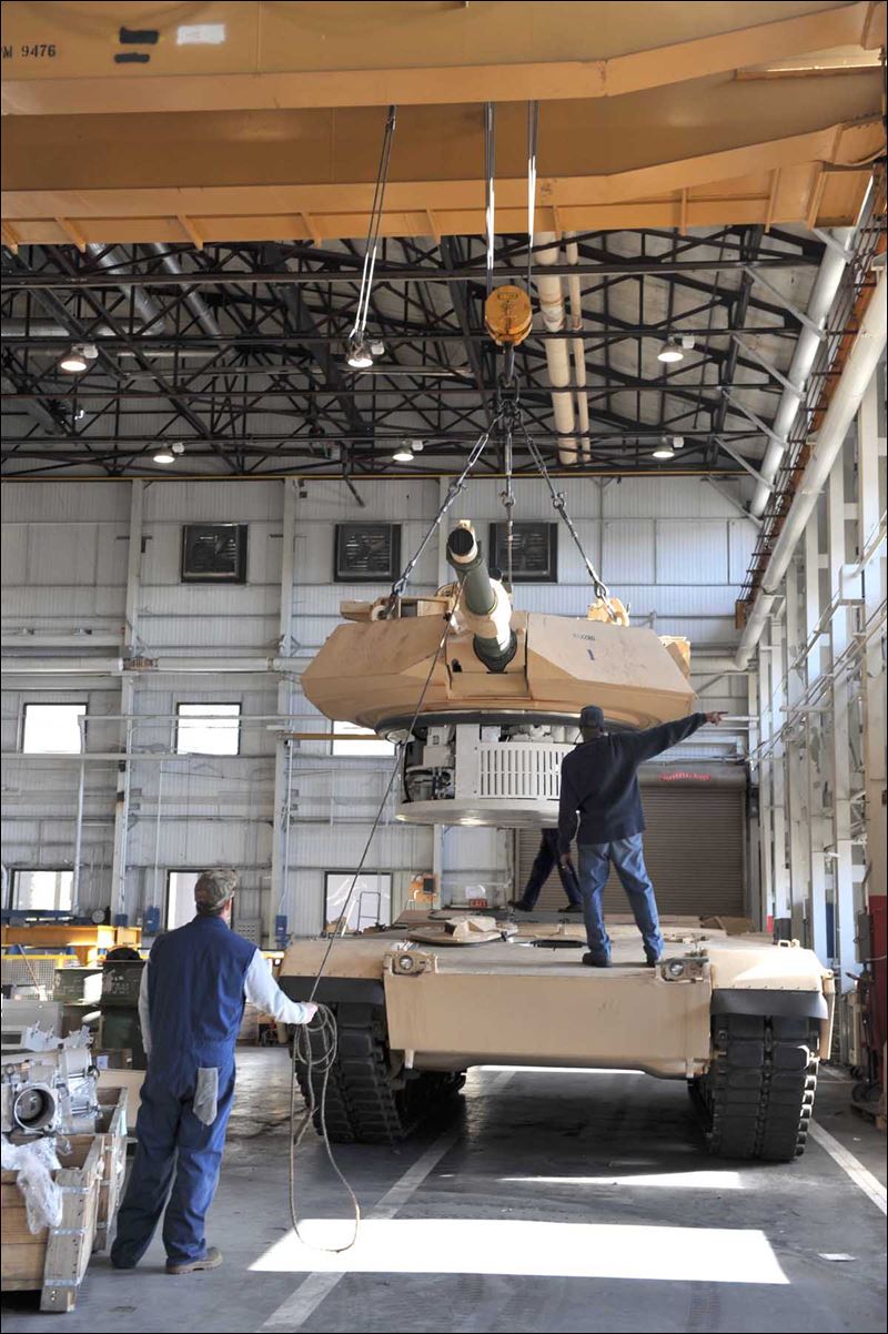
FYI, this image from the web shows an overhead crane lifting a turret into place using the three lifting brackets bolted to the turret top:
I can't find a good picture yet, but I'm pretty sure the third set of bracket bolts are right between and behind the Commander's Hatch and the Loader's Hatch, just in front of the Blast Panels.
HTH
The following images from Prime Portal hopefully will answer your questions:
This image shows a M1A1 with a spare road wheel mounted on the "man-hole cover" in front of the Loader's Hatch:
There are three threaded bosses or welded on hex nuts on the cover top that allow one or two bolts to hole a spare road wheel or drive sprocket in place.
A close up of a spare road wheel in place. Note the 4 bolt heads in front of the "man-hole cover". These are for mounting lifting brackets to lift the turret from the hull.
For M1A2s, the "man-hole cover" has a the Commander's Independent Thermal Viewer (CITV) installed so 1 or 2 of the lifting bracket bolts are used instead:
This view shows the 4 bolts just to the left of the CITV:
This image shows 3 bolts removed and 1 loose, likely for installing a spare road wheel or drive sprocket:
This image from the web is of a M1A1 prototype which has a M1 turret without the "man-hole cover" and shows the 4 bolts for the lifting brackets on each side of the turret:
FYI, this image from the web shows an overhead crane lifting a turret into place using the three lifting brackets bolted to the turret top:
I can't find a good picture yet, but I'm pretty sure the third set of bracket bolts are right between and behind the Commander's Hatch and the Loader's Hatch, just in front of the Blast Panels.
HTH
iowabrit
Member Since: November 06, 2007
entire network: 585 Posts
KitMaker Network: 18 Posts
Posted: Tuesday, November 19, 2013 - 03:56 PM UTC
Thanks for those Jeff. The sprocket ring in the pic certainly seems to be using one of those bolts. I shall have to match a spare wheel to the bolt heads to see if it's feasible.

Tankrider
Member Since: October 07, 2002
entire network: 1,280 Posts
KitMaker Network: 74 Posts
Posted: Tuesday, November 26, 2013 - 02:53 AM UTC
Steve,
Using the outermost bolt in front of the CITV mount should work for you, if you do not decide to use the CITV mount itself, per Jeff's third picture. Tank Crews will use either place to mount spare roadwheels as well as sprockets. If two or more roadwheels are mounted, then the rails on the side of the turret, behind the boxes is a good place...
Jeff,
The third set of attachment points is between and behind the TC's and loader's hatches.
John
majjanelson
Member Since: December 14, 2006
entire network: 1,355 Posts
KitMaker Network: 336 Posts
Posted: Tuesday, November 26, 2013 - 05:33 AM UTC
John,
Thank you for the confirmation.
I've found what appears to be a 4-bolt pattern in some scale plans, and a bolt or 2 in a few pictures, but no pictures that clearly show the area in question. I'll have to take a pic the next time I drill at our Training Site.
Thank you for the confirmation.
I've found what appears to be a 4-bolt pattern in some scale plans, and a bolt or 2 in a few pictures, but no pictures that clearly show the area in question. I'll have to take a pic the next time I drill at our Training Site.
 |

WEB HOSTING BY


Copyright ©2021 KitMaker Network and Kitmaker Network, a subsidiary of Silver Star Enterprises
All Rights Reserved. Please read our Conditions of Use and Privacy Policy.
All Rights Reserved. Please read our Conditions of Use and Privacy Policy.