_GOTOBOTTOM
Scratchbuilders!: Automotive
This is a group for automotive scratchbuilding questions, topics and projects.
Hosted by Mike Kirchoff
1/24th Tracked Vehicle Suspension Q's
casper
Visit this Community
Nelson, New Zealand
Member Since: August 01, 2005
entire network: 395 Posts
KitMaker Network: 152 Posts
Posted: Tuesday, December 04, 2007 - 11:56 PM UTC
Hi all,
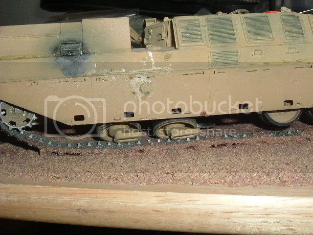
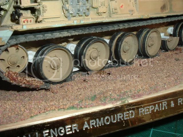
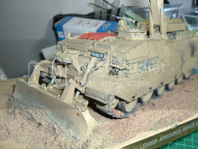
Just playing with the idea of doing a tracked vehicle and I'm just looking for suggestions/ideas on constructing the suspension (this will be my 1st tracked vehicle - I normally work with wheeled vehicles).
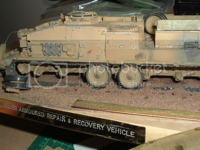
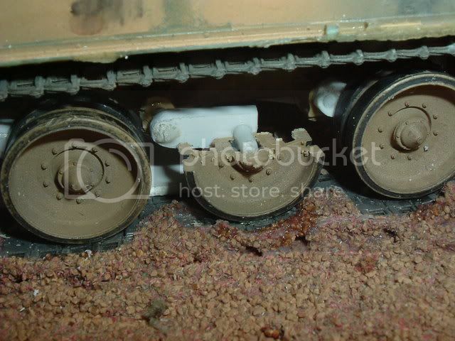
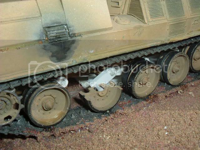
The vehicle in question is the Foremost Chieftain and has Integral Coil Torsional Springs with Upper and Lower Stops, however I may go for its bigger brothers(Foremost Pioneer) setup which has Independant Crankarm with Torsional Coil Spring (the same as a Tank - I do believe !).
So any advise on how to go about building this setup ?
Any thoughts/suggestions gratefully appreciated.

This is the 1:1 version:

matt
Staff MemberCampaigns Administrator
Visit this Community
New York, United States
Member Since: February 28, 2002
entire network: 5,957 Posts
KitMaker Network: 2,626 Posts
Posted: Wednesday, December 05, 2007 - 12:20 AM UTC
Normally the torsion bar suspension is inside the Hull. It's hard to say from the little I can see in the pic how they do it. there are other Vehicles that ise a Exposed torsion bar suspension... IE some Toyota Pickups.

I can't find any good pics of the undercarrige..............

I Did find some in 1/87th scale.......
http://www.dk-models.purespace.de/danies.htm
casper
Visit this Community
Nelson, New Zealand
Member Since: August 01, 2005
entire network: 395 Posts
KitMaker Network: 152 Posts
Posted: Wednesday, December 05, 2007 - 04:03 AM UTC
Thanks for that Matt.
The Torsion Bars are internal (that I've worked out from various pic's), but I'm hoping someone may have ideas on the best way to build the 'crankarms'.
Heres a very basic line drawing of the Chieftain and a line drawing of the Nodwell 240 (part of the Foremost Group), they use similar setups as far as I can tell:


They have a narrow hull so assume that the 'crankarms' must be on some type of extension tube system ? (open to suggestions here folk's).
So any ideas on the best way to build these items ?.
TIA.
matt
Staff MemberCampaigns Administrator
Visit this Community
New York, United States
Member Since: February 28, 2002
entire network: 5,957 Posts
KitMaker Network: 2,626 Posts
Posted: Wednesday, December 05, 2007 - 04:31 AM UTC
My guess is thay're similar to any other torsion bar setup........
http://en.wikipedia.org/wiki/Torsion_bar Some kind of Arm ont he outside of the Hull with the wheel on the opposite end from the torsion bar.
the limiting portion might be internal as well....... but could be some sore of External feature
barv
Visit this Community
Scotland, United Kingdom
Member Since: December 24, 2004
entire network: 1,594 Posts
KitMaker Network: 0 Posts
Posted: Wednesday, December 05, 2007 - 05:45 AM UTC

Hi Rodger ,
Had the same prob a while ago when I had to repair a Chally ----hope these pics help --save s explaning -----(Rod and bar)


Love the beasty
aye
BARV
(GOSMG)
casper
Visit this Community
Nelson, New Zealand
Member Since: August 01, 2005
entire network: 395 Posts
KitMaker Network: 152 Posts
Posted: Wednesday, December 05, 2007 - 06:23 AM UTC
Thanks again Matt and thanks Steve.
Just found a couple more pic's and on closer inspection it looks like the vehicle may have small box sponsons extending from the hull and the 'crankarms' then attach to the 'roadwheels'. By the way the tracks are 1120mm (44") wide.
Been scratching my balding head and think I may drop down the scales to 1/32nd (be a load for the Mack I'm doing ), then I can scavenge some 1/35 suspension parts. Save a bit of hassle. Just means I'll have to rethink my track build idea .
Anyways, thanks again gents.
 _GOTOTOP